How Hot Runner Manifolds Work, Why They Matter, and What Affects Performance
Hot Runner Manifolds: When most people think about hot runner systems, they focus on visible outcomes – faster cycles, no runner scrap, and improved part quality. But inside the mold, the component responsible for making all of that possible is the manifold.
The manifold is where molten plastic is received, divided, and delivered to each cavity through a network of internal channels. It determines how evenly material flows, how stable temperatures remain, and how consistent each cavity fills.
A hot runner system can only perform as well as its manifold allows.

Contact +1 (908) 281-0055 or sales@polymercleaning.com to discuss your Hot Runner Systems today! Experts in High Quality Hot Runner Parts, Repair, & Maintenance for all OEM.
What is a Hot Runner Manifold: A Brief Summary
A hot runner manifold is the central distribution component of a hot runner system, responsible for routing molten plastic from the injection molding machine to each cavity. Its design directly impacts flow balance, temperature control, part quality, and long-term system reliability.
It performs three core functions:
- receives molten plastic from the machine nozzle
- distributes melt through internal channels
- maintains temperature stability across all flow paths
Hot Runner Manifold FAQ
What does a hot runner manifold do?
A hot runner manifold distributes molten plastic from the injection molding machine to multiple nozzles within the mold, ensuring consistent flow to each cavity.
Why is manifold balance important?
Manifold balance ensures that each cavity fills evenly. Poor balance can lead to part inconsistencies, weight variation, and quality issues.
What is the difference between natural and artificial balance?
Natural balance uses equal flow paths to each cavity, while artificial balance adjusts channel sizes or flow conditions to compensate for uneven layouts.
What causes hot runner manifold leakage?
Leakage is typically caused by seal failure, thermal expansion issues, improper alignment, or worn components at connection points.
How does thermal expansion affect manifolds?
As the manifold heats up, it expands. If not properly accounted for, this can lead to stress, misalignment, or leakage.
How do you know if a manifold is failing?
Signs of manifold issues include uneven cavity fill, pressure inconsistencies, material degradation, or visible leakage inside the mold.
Can a hot runner manifold be repaired?
Yes, manifolds can often be repaired or refurbished depending on the level of wear, contamination, or damage.
What materials are hot runner manifolds made from?
They are typically made from hardened tool steels designed to withstand high temperatures and pressures.
👉 Read our Hot Runner Manifold Cleaning & Maintenance Guide
How a Hot Runner Manifold Works
The manifold acts as a controlled melt distribution network inside the mold.
Process Flow
| Step | What Happens |
|---|---|
| 1 | Molten plastic enters the manifold inlet |
| 2 | Melt flows through internal channels |
| 3 | Flow is divided across multiple drops |
| 4 | Nozzles deliver melt into cavities |
| 5 | Manifold remains molten for next cycle |
Tip: Even minor variations in channel geometry can significantly affect flow balance across cavities.
👉 Learn how hot runner systems work → (What is a Hot Runner?)
Why the Manifold Is Critical
The manifold directly influences:
- cavity-to-cavity balance
- pressure distribution
- melt temperature stability
- residence time
- part consistency
Impact of Manifold Performance
| Area | Effect |
|---|---|
| Flow Balance | Determines fill consistency |
| Thermal Stability | Prevents degradation |
| Pressure Drop | Affects injection behavior |
| Residence Time | Influences material quality |
Common Failure Pattern:
Uneven cavity fill is often incorrectly attributed to the machine, when the root cause is actually manifold imbalance.
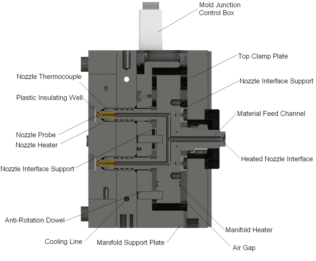
Core Components of a Hot Runner Manifold
The Internal Structure That Controls Flow, Heat, and Reliability. A hot runner manifold is not a single component; it is a precision-engineered assembly made up of multiple integrated elements, each responsible for maintaining thermal stability, flow consistency, and mechanical integrity.
While the manifold is often viewed as a “distribution block,” its performance depends entirely on how well these internal components work together under operating conditions that include:
- high temperatures (200–350°C+)
- constant thermal cycling
- high injection pressures
- varying material viscosities
Understanding each component at a deeper level is critical, especially when diagnosing issues that are often incorrectly attributed to machines, materials, or processing conditions.
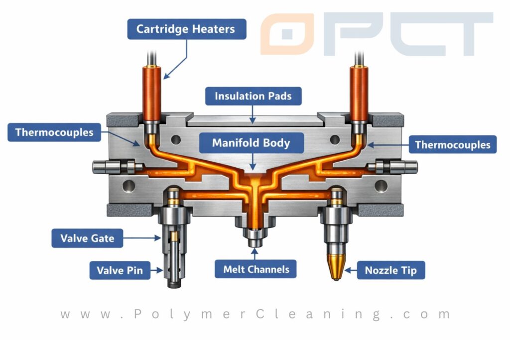
Manifold Body
The Structural and Thermal Foundation
The manifold body is the central steel block that houses all internal flow paths and supports the entire system.
It must withstand:
- continuous exposure to elevated temperatures
- repeated thermal expansion and contraction
- mechanical loads from mounting, sealing, and nozzle interfaces
Key Responsibilities
| Function | Description |
|---|---|
| Structural Integrity | Maintains alignment under thermal and mechanical stress |
| Thermal Conduction | Distributes heat evenly across zones |
| Component Integration | Supports heaters, thermocouples, and drops |
Material Considerations
| Material | Advantage |
|---|---|
| H13 Tool Steel | High thermal fatigue resistance |
| 420 Stainless | Corrosion resistance |
| Specialty Alloys | Improved wear or thermal properties |
Pro Tip:
Material selection directly affects how the manifold responds to thermal cycling — poor material choice can lead to warping, cracking, or long-term instability.
Common Failure Pattern:
Over time, repeated thermal cycling can cause micro-distortion in the manifold body, leading to sealing issues at nozzle interfaces.
Melt Channels
The Hidden Flow Network
Melt channels are the internal pathways that carry molten plastic through the manifold.
They are typically:
- drilled and plugged
- precision-machined
- engineered for flow balance and pressure control
Channel Design Factors
| Factor | Impact |
|---|---|
| Diameter | Affects pressure drop |
| Length | Influences balance |
| Surface Finish | Impacts flow resistance |
| Geometry | Determines dead zones |
Critical Considerations
- shear rate control
- residence time
- avoidance of stagnation areas
Pro Tip:
Even slight variations in channel geometry can create measurable differences in cavity fill behavior — especially in high-cavitation molds.
Common Failure Pattern:
Dead spots or sharp transitions in melt channels can trap material, leading to carbon buildup, degradation, and contamination.
Heaters
Maintaining Thermal Stability
Heaters are responsible for maintaining the manifold at the correct processing temperature.
Without consistent heating, the entire system becomes unstable.
Heater Types in Manifolds
| Heater Type | Function |
|---|---|
| Cartridge Heaters | Primary manifold heating |
| Tubular Heaters | Uniform heat distribution |
| Custom Heaters | Optimized layouts |
What Heaters Control
- melt viscosity
- flow consistency
- startup behavior
- material degradation risk
Pro Tip:
A heater can be electrically functional but thermally inefficient — uneven heat transfer is a common hidden issue.
Common Failure Pattern:
Localized heater degradation creates hot and cold zones, leading to inconsistent melt behavior across cavities.
Thermocouples
The Feedback System for Temperature Control
Thermocouples provide real-time temperature data to the controller, allowing the system to maintain stable operating conditions.
They are typically positioned:
- near heaters
- close to critical melt zones
- within drilled sensor pockets
Key Functions
| Function | Why It Matters |
|---|---|
| Temperature Monitoring | Maintains consistency |
| Feedback Loop | Enables control system response |
| Fault Detection | Identifies thermal issues early |
Pro Tip:
Thermocouples measure steel temperature — not melt temperature — so placement and calibration are critical.
Common Failure Pattern:
Thermocouple drift often leads to overheating, which accelerates polymer degradation and increases maintenance frequency.
Nozzle Interfaces (Drops)
Where Distribution Becomes Delivery
The nozzle interface – often referred to as the “drop” – is where the manifold connects to the nozzle and transfers molten plastic into the next stage of the system.
This is one of the most critical sealing and alignment points in the entire hot runner system.
Key Responsibilities
- ensure proper melt transfer
- maintain sealing under pressure
- accommodate thermal expansion
- align precisely with nozzle components
Design Considerations
| Factor | Impact |
|---|---|
| Alignment | Prevents leakage |
| Contact pressure | Ensures sealing |
| Thermal interface | Maintains temperature consistency |
Pro Tip:
Even minor misalignment at the drop can lead to long-term leakage or uneven thermal behavior.
Common Failure Pattern:
Leakage at nozzle interfaces is often caused by a combination of thermal expansion and improper seating – not just seal failure alone.
👉 View PCT Nozzle Housings 👉 View PCT Nozzle Tips
Insulation / Support Features
Managing Heat and Expansion
Hot runner manifolds operate inside cooled mold plates, which creates a constant battle between heat retention and heat loss.
Insulation and support features are designed to:
- minimize heat transfer into mold plates
- maintain stable thermal zones
- allow controlled expansion
Key Elements
| Component | Function |
|---|---|
| Insulation Pads | Reduce conductive heat loss |
| Air Gaps | Provide thermal separation |
| Support Pads | Maintain structural positioning |
Without proper insulation:
- heat dissipates into the mold
- temperature zones become unstable
- energy consumption increases
- operators compensate by raising temperatures
Tip: Poor insulation is one of the most overlooked causes of inconsistent processing conditions.
Common Failure Pattern: Excessive heat loss leads to operators increasing temperature settings, which accelerates material degradation and shortens component life.
👉 Learn more about Hot Runner Components (“Hot Runner Parts Guide“)
How These Components Work Together
Each component contributes to one of three system-critical functions:
System Function Breakdown
| Function | Components |
|---|---|
| Thermal Control | Heaters, thermocouples, insulation |
| Flow Control | Melt channels, manifold geometry |
| Mechanical Integrity | Manifold body, drops, supports |
A failure in any one area will almost always affect the others.
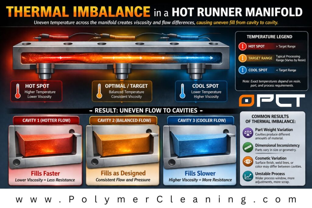
Natural vs Artificial Balance
Flow balance is one of the most important aspects of manifold design because it directly determines whether each cavity sees the same melt conditions at the same time.
In a multi-cavity mold, the manifold is not just splitting flow – it is trying to split flow evenly. If one cavity receives melt faster, hotter, or with less pressure loss than another, the result can be part weight variation, dimensional inconsistency, cosmetic differences, or processing instability. That is why flow balance is a core design objective in hot runner manifolds, not just a secondary layout detail.
Balance Comparison
| Type | Description | Advantage | Limitation |
|---|---|---|---|
| Natural | Equal flow paths | Simple, predictable | Less flexible |
| Artificial | Adjusted geometry | Flexible layout | Requires precision |
A balanced manifold is designed so that molten plastic reaches each drop under as close to the same conditions as possible. In practical terms, that usually means controlling:
- flow path length
- channel diameter and geometry
- pressure drop across each branch
- melt temperature consistency
- shear exposure and residence time
When these factors are controlled correctly, cavities tend to fill more uniformly. When they are not, the machine may appear to be the problem even though the real issue is inside the manifold itself. That fits the article’s broader point that uneven cavity fill is often incorrectly blamed on the press when manifold imbalance is the actual root cause.
Natural Balance
Natural balance uses equal or near-equal flow paths so the melt has a similar travel distance and resistance on its way to each cavity.
This is generally the most straightforward balancing method because the manifold layout itself does much of the work. When the system is geometrically balanced, flow behavior is easier to predict, and the design is often more forgiving during processing. That simplicity is the main advantage of natural balance.
However, natural balance is not always possible. Real mold layouts are often constrained by cavity spacing, part geometry, machine nozzle location, or mold construction limits. In those cases, maintaining equal path lengths may be impractical or impossible.
Artificial Balance
Artificial balance is used when the physical layout cannot be naturally balanced.
Instead of relying on equal flow path lengths, the design compensates by adjusting internal geometry or flow conditions. This may include changing channel diameters, modifying branch geometry, or making other engineered corrections so each cavity still sees comparable resistance and fill behavior even in an uneven layout.
The major benefit of artificial balance is design flexibility. It allows more complex mold layouts, unusual cavity arrangements, and packaging constraints that would be difficult to solve with natural balance alone.
The tradeoff is precision. Artificial balance requires more careful engineering because small errors in geometry can create measurable differences in cavity fill behavior — especially in high-cavitation molds or tighter process windows. That is fully consistent with the article’s earlier warning that even minor variations in channel geometry can significantly affect flow balance.
Thermal Behavior and Expansion
Hot runner manifolds operate in one of the most demanding thermal environments inside the mold.
Unlike the surrounding mold plates, which are intentionally cooled, the manifold must stay hot enough to keep the polymer molten and flowing consistently. In many systems, the manifold operates around 200-350°C while nearby mold plates may remain closer to 20–80°C. That temperature gap is not just a design detail; It is one of the main engineering challenges in hot runner performance.
Temperature Ranges
| Area | Typical Temperature |
|---|---|
| Manifold | 200-350°C |
| Mold Plates | 20-80°C |
Because steel expands as it heats, the manifold is constantly trying to grow in size during heat-up and production. The mold, meanwhile, is trying to stay dimensionally stable under much cooler conditions. This creates a built-in mechanical conflict that must be accounted for in the design of the manifold body, nozzle interfaces, supports, and sealing surfaces.
In other words: a hot runner manifold is not just a flow component — it is a flow component that is moving slightly every time the system heats up.
Expansion Risks
As the manifold expands, several things have to remain under control at the same time:
- melt channels must stay properly aligned with drops and nozzles
- sealing faces must maintain enough contact pressure to prevent leakage
- support points must allow controlled movement without creating distortion
- heaters and thermocouples must continue to deliver stable temperature control
If expansion is not properly managed, the system may still run – but it will run inconsistently, and those inconsistencies usually show up as quality problems, maintenance issues, or premature component wear.
| Issue | Result |
|---|---|
| Misalignment | Flow inconsistency |
| Seal failure | Leakage |
| Stress | Component damage |
These failures are rarely isolated. A small amount of thermal growth can reduce sealing pressure at one interface, which may then cause leakage, carbon buildup, uneven heating, and eventually damage to surrounding components. What starts as a thermal issue often becomes a flow and maintenance issue as well.
Real-World Effects of Poor Thermal Control
When thermal behavior is not well managed, manufacturers may begin to see:
- intermittent leakage during startup or shutdown
- cavity-to-cavity variation caused by shifting flow conditions
- unstable processing windows as operators compensate with temperature changes
- excessive wear at nozzle seats, sealing surfaces, or support pads
- long-term distortion that makes repeatable assembly more difficult
This is one reason hot runner leaks can be frustrating to diagnose. The root cause is not always a “bad seal” by itself. In many cases, the seal is failing because thermal expansion, support conditions, or interface alignment were not fully under control.
Common Failure Pattern:
Thermal expansion issues often show up first during startup cycles, when components are heating at different rates and the system has not yet reached a stable thermal condition. A manifold may appear sealed when cold, shift during heat-up, and then produce intermittent leakage before the system fully stabilizes.
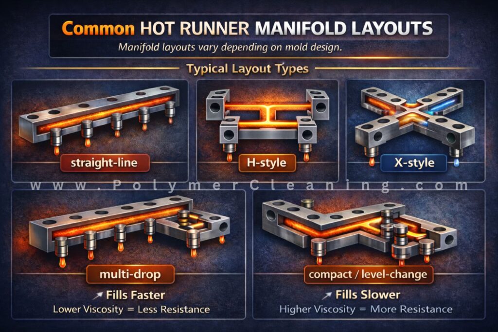
Common Hot Runner Manifold Layouts
Manifold layouts vary depending on mold design.
Typical Layout Types
- straight-line
- H-style
- X-style
- multi-drop
- compact / level-change
Layout Considerations
| Factor | Impact |
|---|---|
| Cavity count | Determines complexity |
| Gate location | Controls drop placement |
| Mold size | Limits layout |
| Balance requirements | Affects symmetry |
How Manifolds Affect Part Quality
The manifold influences the melt before it reaches the gate.
Quality Impact Areas
| Factor | Effect |
|---|---|
| Temperature variation | Inconsistent flow |
| Flow imbalance | Weight variation |
| Degradation | Cosmetic defects |
| Pressure variation | Fill issues |
Pro Tip:
If defects appear across multiple cavities, the issue is often upstream — not at the gate, but in the manifold.
Common Hot Runner Manifold Failures & Maintenance Procedures
Failure Modes
| Problem | Cause | Result |
|---|---|---|
| Uneven fill | Poor balance | Part variation |
| Leakage | Seal/expansion issue | Mold damage |
| Degradation | Overheating | Burn marks |
| Dead zones | Poor flow design | Contamination |
Manifold Maintenance Basics
Manifolds require periodic inspection and cleaning.
Keeping hot runner manifolds clean and well-maintained is essential for any injection molding operation that prioritizes efficiency, product quality, and cost-effectiveness. Leading brands offer systems with advanced monitoring and maintenance capabilities, enabling manufacturers to take a proactive approach to manifold care.
By following best practices for cleaning, temperature management, and wear monitoring, businesses can ensure that their hot runner systems continue to perform at a high level, meeting production demands and maintaining competitive advantage.
Click the link below for a full Hot Runner Manifold Cleaning & Maintenance Guide
Quick Maintenance Checklist
| Task | Purpose |
|---|---|
| Heater testing | Detect failures |
| Thermocouple check | Ensure accuracy |
| Cleaning | Remove buildup |
| Inspection | Prevent downtime |
👉 View Hot Runner Manifold Cleaning & Maintenance Guide
Repair vs Replacement
Quick Decision Table
| Condition | Recommended Action |
|---|---|
| Minor contamination | Clean |
| Heater failure | Repair |
| Wear at interfaces | Refurbish |
| Severe damage | Replace |
Manifolds Don’t Fail Alone
A manifold issue is rarely isolated. Understanding the system as a whole is critical.
Polymer Cleaning Technology is here to help!
Polymer Cleaning Technology: Leading the Way in Hot Runner Services and Parts
With a reputation for precision and reliability, PCT helps manufacturers keep their hot runner systems operating at peak performance.
Services Offered
Hot Runner Cleaning
Specialized chemical-free cleaning systems remove polymer residue without damaging metal surfaces.
Hot Runner Maintenance
Thorough Inspection, Testing, Analysis, Assembly, and Comprehensive Reports.
Preventive Maintenance Programs
Tailored service schedules to suit production environments.
Component Repair & Refurbishment
Includes manifolds, heaters, nozzles, and temperature control systems.
Reverse Engineering & Custom Parts
Solutions for hard-to-find or discontinued OEM parts.
Parts Inventory
- Nozzle Tip Insulators
- Heaters (coils, bands, cartridges)
- Thermocouples
- Nozzle Tips
- Valve Pins
- Nozzle Housings
- Valve Bushings
- Pistons & Spacers
- Seal kits (O-Rings)
Related Reading
- Hot Runner Manifold Cleaning & Maintenance Guide
- What is a Hot Runner?
- Hot Runner Parts Guide
*This information is to be used as a general guideline only. Speak to your system manufacturer directly for verified information regarding your Hot Runner System.
*Note: All numerical data and performance examples in this article are drawn from a combination of published supplier datasheets, standard tool-steel references, and aggregated field experience. Where specific case studies are presented, they represent illustrative or typical outcomes, not a controlled laboratory test. Actual results may vary depending on resin chemistry, cycle conditions, and maintenance intervals.
Find this information useful? Share with friends & colleagues:
Contact Information:
Polymer Cleaning Technology, Inc.
sales@polymercleaning.com
+1 (908) 281-0055