Page Menu

A Brief Guide to Hot Runner Manifold Cleaning and Maintenance for Operational Efficiency

(Updated July, 2026)

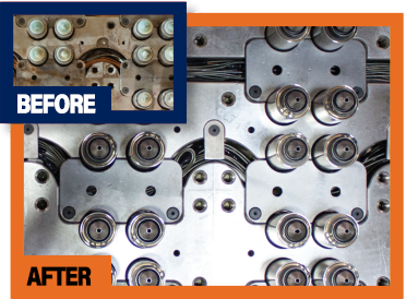
Hot runner manifold cleaning removes degraded resin, pigment residue, carbonized polymer, foreign material, and other contamination from the system’s melt-delivery passages and accessible component surfaces. Depending on the condition of the system, cleaning may range from a controlled material changeover to complete disassembly, flow-channel cleaning, inspection, electrical testing, repair, and reassembly.

Cleaning is not the correct response to every hot runner problem. Leakage, failed heaters, inaccurate thermocouples, worn sealing surfaces, damaged nozzles, valve-component wear, poor alignment, and unsuitable processing conditions can create symptoms that resemble internal contamination.

This guide explains how to recognize possible manifold contamination, compare cleaning approaches, determine what should be inspected, and decide whether the appropriate next step is purging, cleaning, preventive maintenance, repair, refurbishment, or replacement.

Hot Runner Manifold Cleaning

For same-day quotes on all Hot Runner Cleaning, Hot Runner Repair, Hot Runner Manifold Maintenance, Nozzle & Power Lead Repair and more Hot Runner Services contact Polymer Cleaning Technology at sales@polymercleaning.com or (908) 281-0055 today!

Hot Runner Manifold Cleaning Guide

What is a Hot Runner Manifold?

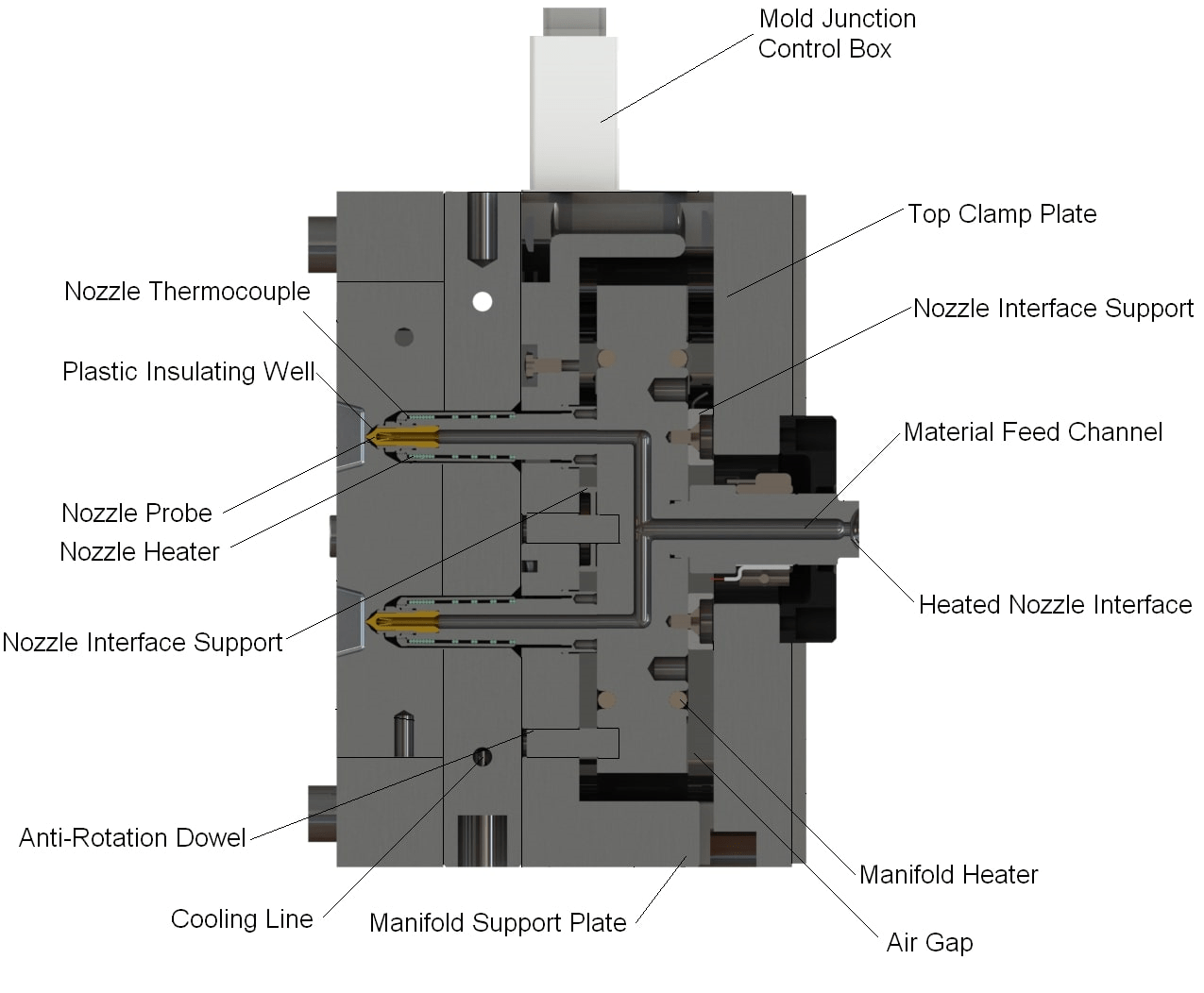
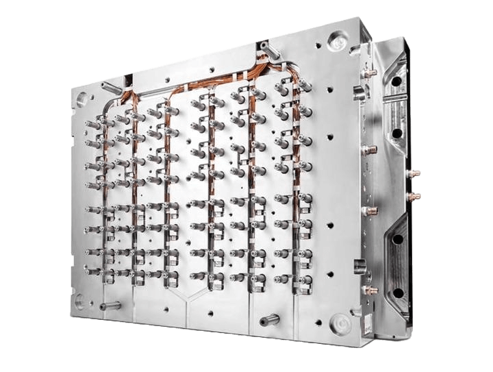
A hot runner manifold is the heated distribution component that receives molten polymer from the injection molding machine and routes it through internal melt channels to the system’s nozzles. Those nozzles then deliver the material toward the mold cavities.

Hot Runner Manifold

For the system to operate consistently, the manifold must maintain controlled melt flow while its heaters, thermocouples, interfaces, supports, and surrounding mold structure function as designed. Resin that remains in low-flow areas, experiences excessive heat history, leaks into unintended spaces, or degrades during interruptions can become a source of contamination.

This guide focuses specifically on cleaning and maintenance. For a complete explanation of manifold construction, flow balance, thermal behavior, and design, read Hot Runner Manifolds Explained.

Safety Before Cleaning or Disassembling a Hot Runner System

Hot runner maintenance should be performed by trained personnel using the system manufacturer’s drawings, service instructions, torque requirements, electrical specifications, and approved procedures.

A hot runner assembly may involve:

  • High temperatures
  • Stored hydraulic or pneumatic pressure
  • Electrical energy
  • Heavy mold plates
  • Residual molten polymer
  • Spring-loaded or actuated components
  • Delicate sealing and alignment surfaces
  • Precisely fitted heaters, sensors, pins, bushings, and nozzles

Applicable plant procedures may require lockout/tagout, electrical isolation, pressure relief, verified cooling, suitable lifting equipment, personal protective equipment, and confirmation that stored energy has been controlled. OSHA’s hazardous-energy standard covers servicing and maintenance where unexpected startup or the release of stored energy could injure employees.

Do not treat this article as a universal disassembly manual. Follow OEM documentation and facility safety procedures before working on any system. For a general overview of the documentation and organization involved, see Proper Hot Runner Disassembly in 8 Steps.

Quick Answer: When Does a Hot Runner Manifold Need Cleaning?

A hot runner manifold may need cleaning when one or more of the following conditions persist:

  • Black specks or burned particles in molded parts
  • Recurring color streaks after a material change
  • Unexplained contamination
  • Increasing purge time
  • Burned or degraded resin during startup
  • A suspected restriction in one or more melt paths
  • Changes in injection pressure or fill behavior
  • Recurring cavity-to-cavity variation
  • Evidence of internal polymer leakage
  • A long shutdown or unknown storage history
  • Contamination that returns after normal processing adjustments

These symptoms do not prove that the manifold is dirty. Similar problems can originate from the barrel, screw, check ring, resin-handling system, nozzles, tips, gates, heaters, thermocouples, valve components, venting, or molding conditions.

View a General Step-by-Step Quick Guide Below

Start by documenting the symptom and narrowing the likely inspection areas with PCT’s Hot Runner Troubleshooting Assistant


Different Types of Hot Runner Manifold Cleaning Processes

“Cleaning a manifold” can describe several very different interventions. They should not be treated as interchangeable, as each is it’s own specific process with very differing steps.

Level of interventionWhat it addressesIs disassembly normally involved?Main limitationAppropriate use
In-process purgingDisplaceable resin, color, or limited residue in the active melt pathNoCannot verify internal surfaces or remove every hardened depositPlanned material or color change
External surface cleaningResidue on accessible exterior surfacesSometimes limitedDoes not clean internal channelsMaintenance after safe access
Component-level cleaningResidue on removed nozzles, tips, pins, bushings, or related partsUsually partialDoes not necessarily address the manifold bodyLocalized contamination or component service
Manifold flow-channel cleaningPolymer or carbonized material inside internal passagesOftenCompatibility and access depend on manifold constructionSuspected internal buildup or restriction
Complete hot-runner cleaningManifold, nozzles, interfaces, accessible channels, and related componentsUsually substantialRequires documentation, handling, and qualified reassemblyWidespread contamination or unknown system condition
Cleaning with inspection and testingContamination plus electrical, mechanical, sealing, and wear evaluationYes in many casesMore involved than cleaning alonePreventive maintenance or recurring production faults
Repair or refurbishment serviceCleaning plus component repair, replacement, machining, or restorationYesScope depends on damage and part availabilityLeakage, wear, electrical damage, or repeated failure

Purging may be sufficient for a routine color change but insufficient when material has carbonized, entered a leakage path, collected behind a component, hardened in a low-flow region, or concealed damage to a sealing interface.

Professional Hot Runner Cleaning Services from PCT


Contamination and Buildup Inside a Hot Runner Manifold: Why This Occurs

Excessive residence time

Polymer continues to experience heat while it remains inside the barrel, manifold, nozzles, and tips. If material remains at temperature longer than its processing stability allows, it may discolor, change viscosity, generate degradation products, or form residue.

The relevant limit depends on the resin grade, temperature history, additives, moisture condition, system volume, shot size, and flow behavior. It should not be reduced to one universal residence-time rule.

Repeated overheating or thermal instability

An overheated zone, temperature overshoot, poor heater contact, inaccurate thermocouple feedback, or unsuitable setpoint can expose resin to excessive thermal stress.

The apparent cause may be contamination, but the underlying fault may be:

  • A failing heater
  • A displaced thermocouple
  • Incorrect controller configuration
  • Poor electrical connections
  • A damaged lead
  • Heat loss around an interface
  • Incorrect process settings

Startup and shutdown practices

Material left inside a hot runner during an unsuitable shutdown can continue to degrade. The next startup may then release discolored or carbonized material into production.

Startup and shutdown requirements vary by resin and system, all exact sequences and temperatures should be checked against the resin supplier and hot-runner manufacturer.

Material and color changes

Pigments and previous resin can remain in low-velocity areas or adhere to internal surfaces. A replacement material with different viscosity, processing temperature, or chemical compatibility may not displace the previous material efficiently.

Incompatible transitions can also create their own degradation or contamination problem. Review the outgoing resin, incoming resin, acceptable processing window, and approved purging approach before the change.

Dead spots and low-flow regions

Material can remain longer in areas with limited flow. A low-flow area may result from:

  • System geometry
  • A restricted channel
  • A worn or damaged component
  • Leakage
  • Poor alignment
  • An inactive cavity
  • An unsuitable operating condition

Cleaning may remove the resulting residue, but it will not correct a recurring geometric, wear, or alignment condition.

Internal leakage

Polymer that escapes its intended melt path can spread across sealing faces, heater areas, wiring channels, nozzle interfaces, plate pockets, or control components. Once leakage occurs, cleaning alone may not be sufficient. The leakage source must also be identified and corrected.

Moisture and foreign contamination

Incorrectly dried resin, contaminated regrind, foreign particles, mixed materials, degraded purge material, and poor material-handling discipline can all introduce defects that may be mistakenly attributed to the manifold.

BASF’s injection-molding troubleshooting resources distinguish black specks, color streaks, moisture streaks, burning, short shots, and mold deposits as separate defect categories with multiple possible causes.

Filled and abrasive materials

Glass fibers, minerals, flame retardants, pigments, and other additives can alter wear, flow, adhesion, and cleaning behavior. Residue found while processing a filled resin may coexist with:

  • Channel wear
  • Coating damage
  • Tip wear
  • Valve-component wear
  • Erosion
  • Seal damage

In these cases, restoring cleanliness without evaluating surface condition may leave the actual fault unresolved.

Previous incomplete cleaning

A partial cleaning may remove loose residue while leaving material in internal passages, interfaces, dead spaces, plugs, or component pockets. If symptoms return quickly, technicians should question whether:

  1. The contamination source was removed.
  2. The complete affected area was accessible.
  3. The underlying thermal, leakage, material, or wear condition was corrected.

For a broader review of contamination sources, see resources such as Top Causes of Contamination in Hot Runner Systems.


Signs Your Manifold May Need Cleaning

Part-quality symptoms

Possible contamination-related symptoms include:

  • Black specks
  • Dark streaks
  • Previous-color carryover
  • Burned particles
  • Intermittent discoloration
  • Inconsistent surface appearance
  • Unexplained contamination across multiple cavities
  • Changes in cavity-to-cavity filling

These defects may also be caused by the machine barrel, screw, check ring, nozzle, material supply, gate, venting, heater control, or processing conditions.

Processing symptoms

Possible processing indicators include:

  • Longer material or color changeovers
  • Increasing purge quantity
  • Changes in fill pressure
  • Pressure instability
  • A suspected restricted flow path
  • Recurring startup scrap
  • Uneven response between cavities
  • A previously stable process requiring repeated adjustment

A processing change is evidence to investigate, not automatic proof that cleaning is required.

Maintenance and inspection evidence

Cleaning is more directly indicated when inspection finds:

  • Degraded polymer on accessible surfaces
  • Carbonized residue
  • Pigment accumulation
  • Polymer in unintended areas
  • Restricted or blocked passages
  • Residue around channel plugs
  • Contamination at nozzle-to-manifold interfaces
  • Material encapsulating wires or connectors
  • Deposits discovered during scheduled service
Hot Runner Manifolds

“The most common contamination pattern found during a manifold service is concentrated buildup within low-flow or stagnant areas of the melt channels, not an even coating throughout the entire manifold.” (Polymer Cleaning Technology)

“Residue is typically heaviest around sharp transitions, channel intersections, end plugs, nozzle drops, and other areas where material remains at temperature longer than the main flow stream.” (Polymer Cleaning Technology)

Table: Manifold-Contamination Diagnostic

Observed symptomPossible contamination-related explanationOther conditions to checkRecommended next inspection step
Black specksCarbonized resin is releasing into the melt streamBarrel contamination, excessive temperature, long residence time, degraded purge materialCompare when and where the specks appear; review heat history and inspect accessible melt-path areas
Color streakingPrevious pigment or resin remains in a low-flow areaPoor changeover technique, barrel residue, incompatible materials, nozzle-tip pocketsConfirm changeover procedure and determine whether the pattern is isolated or system-wide
Increasing purge timeMaterial is hanging up in the melt pathViscosity mismatch, unsuitable purge method, dead spots, inactive cavitiesReview material transition and compare current purge behavior with historical records
Short shotsA flow path may be restrictedCold zone, blocked gate, machine shot issue, venting, low material temperatureCheck controller data, nozzle zones, gates, material supply, and cavity pattern before disassembly
Uneven cavity fillingOne branch may contain residue or restrictionHeater or thermocouple fault, nozzle restriction, gate variation, manifold balanceIdentify whether the affected cavity follows one thermal zone, nozzle, or manifold branch
Higher injection pressureInternal restriction may be increasing resistanceResin viscosity, material lot, temperature, gate condition, machine calibrationCompare pressure trend with material, temperature, and part-weight data
Burned material after startupResin may have degraded during idle timeBarrel degradation, unsuitable shutdown, overheated zoneTrace whether contamination begins before or after material enters the hot runner
Repeated contamination after purgingHardened residue may remain outside the active swept pathOngoing overheating, leakage, barrel contamination, damaged componentEscalate from process adjustment to documented inspection
Visible internal leakagePolymer has escaped the intended flow pathSeal failure, alignment, thermal expansion, worn interface, assembly errorStop treating the condition as cleaning-only; inspect the sealing and support system
Temperature instabilityBuildup may affect local conditions, but contamination is not the most likely first conclusionHeater, thermocouple, lead, connection, controller, groundingPerform system-specific electrical and thermal checks

Can a Hot Runner Manifold Be Cleaned Without Disassembly?

Only within the limits of what the selected process can reach:

A controlled purge or material changeover may remove,

  • The outgoing resin from actively swept flow paths
  • Loose color residue
  • A portion of material that has not hardened or carbonized
  • Contamination that can be safely displaced under normal operating conditions

Purging cannot reliably,

  • Expose internal surfaces for inspection
  • Verify channel condition
  • Remove polymer that has leaked outside the intended flow path
  • Inspect sealing faces
  • Confirm the condition of channel plugs
  • Evaluate hidden wear
  • Access residue trapped behind removed components
  • Repair heaters, sensors, seals, pins, bushings, or damaged interfaces

A suspected restriction should not automatically be addressed by increasing pressure or forcing material through the system. That response can increase stress without identifying whether the restriction is caused by resin, a cold zone, a damaged component, a gate problem, or an assembly condition.

Common Hot Runner Manifold Cleaning Methods

No single cleaning method is universally safe for every manifold body, heater, thermocouple, coating, seal, thread, channel plug, brazed assembly, or sensor configuration.

Professional hot-runner service facilities may use combinations of specialized disassembly tools, thermal equipment, fluidized systems, ultrasonic systems, electrical testers, machine tools, and measurement equipment. Mold-Masters publicly lists fluidized sand ovens, pyrolysis ovens, ultrasonic equipment, electric ovens, controllers, testers, lifting equipment, and specialty disassembly tools among the equipment used across its service facilities.

The presence of a method in an OEM service facility does not mean that method is suitable for every component.

Table: Hot Runner Manifold Cleaning Methods Compared

MethodBest suited forDisassembly required?Primary advantageMain limitation or risk
Controlled material changeover or purgingDisplaceable resin and pigment in active flow pathsUsually noCan be performed as part of production changeoverCannot inspect hidden surfaces or reliably remove hardened deposits
Manual cleaning of removed, accessible partsLoose residue on compatible component surfacesUsually partialTargeted access and visual controlAggressive tools can scratch, round, gouge, or change precision surfaces
Controlled thermal cleaningPolymer that can be removed through an approved heat-based processCommonly yesCan address residue that is difficult to remove manuallyTemperature exposure must be compatible with component material, heat treatment, coatings, brazing, sensors, and geometry
Fluidized-bed cleaningCertain removed metallic components and residuesUsually yesControlled heat transfer and residue removalNot appropriate for every assembly, coating, sensor, heater, or material
Pyrolysis or controlled bake-outPolymer removal from compatible metallic partsUsually yesCan reduce reliance on aggressive scrapingUncontrolled heating can distort, oxidize, or damage components
Ultrasonic cleaningCompatible removed parts and residue that responds to the selected bathUsually yesReaches complex accessible surfaces through fluid agitationBath chemistry, frequency, temperature, coating, and component construction must be compatible
Verified chemical cleaningSpecific residue and compatible component materialsUsuallyMay address residue that does not respond to other methodsChemical attack, corrosion, coating damage, waste handling, and worker-safety risks
Specialized professional processComplex manifolds, carbonized resin, leakage contamination, or combined maintenanceUsuallyIntegrates documentation, cleaning, inspection, testing, and repair recommendationsRequires accurate system identification, service scope, and qualified reassembly

PCT uses a thermal-based cleaning process to remove carbon buildup, degraded resin, pigment residue, and other contamination from hot runner manifolds, nozzles, gates, and internal flow channels. The process is intended to clean these areas without distorting the manifold or altering its surface finish.

Before Cleaning: Documentation and Baseline Inspection

Effective service begins before residue is removed. Cleaning can erase evidence that helps identify where contamination originated.

Before disassembly or cleaning, technicians should document the system’s received condition.

System identification

  • Manufacturer
  • System model
  • Mold or tool number
  • Serial number when available
  • Number of drops or cavities
  • Gate type
  • Resin and grade
  • Color or additive package
  • Last known production date
  • Previous service history

Production symptoms

  • Which cavities are affected
  • Whether the symptom is continuous or intermittent
  • Whether it occurs at startup, during production, or after a changeover
  • Pressure or temperature trends
  • Recent resin, color, controller, or process changes
  • Previous corrective actions
  • Whether purging changed the symptom

Physical documentation

*Where safe and applicable:

  • Photograph the received assembly.
  • Photograph wiring and connector positions.
  • Label zones and leads.
  • Record component orientation.
  • Protect sealing and alignment surfaces.
  • Identify previous repairs or modifications.
  • Note damaged fasteners, connectors, threads, or covers before removal.

Electrical baseline

*Qualified personnel should establish system-specific baseline readings for:

  • Heater circuits
  • Thermocouples
  • Grounding
  • Leads
  • Connectors
  • Insulation condition
  • Circuit continuity

*All readings should be compared with the system documentation, known historical values, or approved specifications.


Professional Manifold Cleaning and Maintenance Process (Step by Step Guide)

The exact sequence varies by manufacturer, system construction, contamination type, received condition, and requested service scope. A professional workflow may look like:

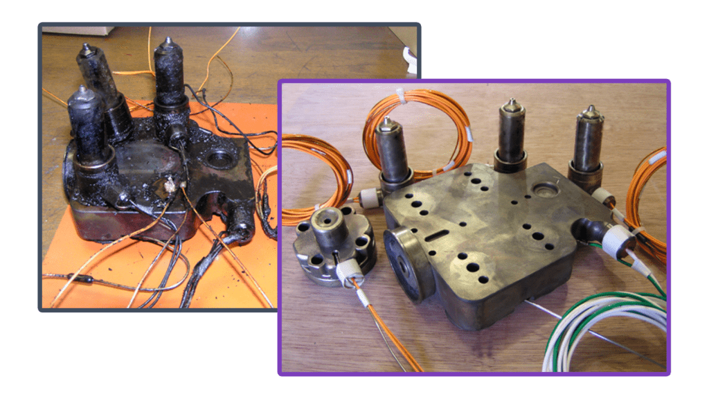
Hot Runner Manifold Cleaning Process

1. Intake and history review
Confirm the system identity, processed resin, production symptoms, known faults, previous repairs, and requested service.

2. Received-condition documentation
Photograph and catalog the assembly, wiring, components, labels, and visible damage.

3. Initial visual inspection
Look for leakage, residue, broken leads, damaged connectors, missing fasteners, impact damage, corrosion, or previous modifications.

4. Baseline electrical evaluation
Record applicable heater, thermocouple, lead, connector, and grounding conditions before disassembly.

5. Controlled disassembly
Follow the system drawing, OEM procedure, plant safety requirements, and documented component organization.

6. Component identification
Label zones, nozzles, pins, bushings, spacers, heaters, thermocouples, seals, and other removable parts where applicable.

7. Residue removal
Select a process compatible with the residue and each component’s material, coating, heat treatment, geometry, electrical construction, and serviceability.

8. Flow-channel inspection
Inspect accessible channels, inlets, outlets, plugs, transitions, and branches for remaining residue, damage, wear, corrosion, or restriction.

9. Interface and sealing inspection
Examine nozzle-to-manifold contacts, sealing faces, supports, spacers, shutoffs, plugs, threads, and evidence of leakage.

10. Electrical and component evaluation
Inspect and test applicable heaters, thermocouples, leads, connectors, and grounding according to approved specifications.

11. Repair recommendations
Separate conditions that can be cleaned from those requiring component replacement, electrical repair, machining, coating evaluation, or further analysis.

12. Controlled reassembly
Reassemble according to system requirements, including approved components, alignment, sequence, clearances, torque values, and documentation.

13. Final testing
Repeat applicable electrical checks and complete any verified functional tests included in the service scope.

14. Service reporting
Provide received-condition findings, cleaning scope, inspection results, components replaced, unresolved conditions, and recommendations.

[PCT INPUT REQUIRED: Identify which of these steps are included in PCT’s standard manifold-cleaning service and which require a PM, repair, or refurbishment scope.]

[ORIGINAL PCT ASSET: Anonymized sample inspection and service report]

Table: What Should Be Inspected While the Manifold Is Apart?

Cleaning creates access to conditions that may not be visible during production. The inspection should be appropriate to the system design.

Inspection areaWhat technicians are looking forWhy it mattersLikely response
Melt channels and inletResidue, restriction, erosion, corrosion, surface damageAffects material flow and contaminationClean, inspect further, repair, or evaluate replacement
Channel plugsLeakage evidence, damage, looseness, prior alterationPlug condition affects channel integrity and sealingClean, repair, replace, or refer to OEM requirements
Nozzle-to-manifold interfacesPolymer leakage, fretting, wear, poor contactCan cause leakage, heat-transfer problems, and alignment issuesClean, restore if feasible, replace affected parts
Sealing facesScratches, dents, erosion, polymer tracks, distortionDamaged faces may continue leaking after cleaningRepair, machine, replace, or further evaluate
Supports, pads, and spacersWear, collapse, fretting, dimensional changeInfluences support, alignment, and thermal expansionReplace, repair, or verify dimensions
HeatersPhysical damage, loose fit, poor contact, lead damage, electrical faultsTemperature-control problems can create degradation or restrictionsRefit, repair, or replace
ThermocouplesDamage, placement issues, loose mounting, unstable readingsIncorrect feedback can cause overheating or cold zonesReinstall, repair connection, or replace
Power leads and connectorsBrittleness, pin damage, contamination, poor terminationCan cause intermittent faults or unsafe operationRepair or replace
Ground connectionsLoose, damaged, contaminated, or missing connectionsRelevant to safe electrical operationRestore according to approved documentation
Nozzles and tipsBlockage, wear, damage, deformation, carbonLocal restrictions can resemble manifold contaminationClean, repair, or replace
Valve pins and bushingsScoring, galling, wear, residue, poor movementCan affect gate operation, leakage, and material retentionClean, polish where approved, repair, or replace
SealsCuts, compression set, hardening, chemical damageDamaged seals can permit leakageReplace with the correct component
Threads and fastenersGalling, stripping, stretching, corrosion, incorrect hardwareAffects reliable assembly and serviceabilityRepair or replace as approved
Coatings and treated surfacesPeeling, erosion, scoring, chemical or thermal damageDamaged coating may change wear or material behaviorSpecialist evaluation, recoating, repair, or replacement
Manifold body and platesCracks, corrosion, distortion, impact damageStructural damage cannot be corrected through cleaningEngineering review, refurbishment, or replacement

For descriptions of the system components mentioned above, use PCT’s Complete Hot Runner Parts Guide rather than expanding this article into another parts encyclopedia.

Table: Cleaning Alone Will Not Fix Every Manifold Problem

A clean system may still fail if the underlying fault is electrical, mechanical, thermal, structural, or process-related.

ConditionIs cleaning likely to help?Additional action to consider
Removable resin or pigment residueYesConfirm source and inspect for recurrence
Carbonized polymer in compatible accessible areasPossiblyVerify complete removal and determine why degradation occurred
Failed heaterNoElectrical diagnosis and replacement or approved repair
Damaged thermocoupleNoVerify circuit, placement, connection, and replacement need
Electrical short or ground faultNoQualified electrical inspection and repair
Internal leakageOnly as part of serviceCorrect sealing, alignment, wear, or assembly condition
Worn sealing faceNoDimensional evaluation, machining, refurbishment, or replacement
Cracked manifold or plateNoEngineering evaluation and likely repair or replacement
Distorted componentNoDimensional inspection and feasibility review
Damaged coatingNoCoating or component specialist evaluation
Worn valve pin or bushingNoRepair, rework, or replacement
Incorrect alignmentNoCorrect assembly, support, dimensions, or damaged parts
Poor manifold balanceNoDesign, process, thermal, or flow analysis
Incompatible processing conditionsNoCorrect material preparation and process settings
Nozzle or gate restrictionNot necessarilyInspect the affected nozzle, tip, gate, and thermal zone
Barrel or screw contaminationNoClean and inspect the machine-side material path
Mold venting problemNoInspect cavity and venting conditions

The diagnostic value of cleaning comes partly from what technicians find during service. If cleaned residue returns, the root cause remains active. When Hot Runner Manifold Cleaning may not be enough, PCT offers Comprehensive Hot Runner Maintenance Services to Repair and Refurbish any make or model.


How Often Should a Hot Runner Manifold Be Cleaned?

There is no universal cleaning interval for every hot runner manifold.

The appropriate maintenance point depends on:

  • Resin chemistry
  • Resin processing window
  • Operating temperature
  • Heat history
  • Production hours and cycles
  • Shot size relative to system volume
  • Color-change frequency
  • Material-change frequency
  • Additives and pigments
  • Glass or mineral content
  • Shutdown frequency
  • Idle periods
  • Historical leakage
  • Known low-flow areas
  • Heater and thermocouple behavior
  • Part-quality trends
  • Previous inspection findings
  • OEM recommendations

Official OEM intervals may apply to specific product families rather than all systems. That is why a calendar-only recommendation such as “clean every year” should not be presented as a universal rule.

A condition-based framework

Consider moving inspection or cleaning forward when:

  • Changeovers consistently take longer than the established baseline.
  • Black specks or color contamination recur.
  • Pressure or fill behavior shifts without another confirmed cause.
  • Temperature zones become unstable.
  • A leak occurs.
  • The mold returns from extended storage.
  • A difficult or heat-sensitive resin campaign ends.
  • A major material transition is planned.
  • A hot half is already being disassembled for other maintenance.
  • Historical records show a repeatable contamination pattern.

Consider extending the interval only when:

  • Production remains stable.
  • Changeovers remain predictable.
  • Electrical readings remain consistent with approved baselines.
  • No leakage is present.
  • Part-quality trends remain stable.
  • Previous inspections show minimal residue or wear.
  • OEM guidance and maintenance history support the decision.

Maintain a manifold service history

  • Service date
  • Production hours or cycles when available
  • Resin and color history
  • Reason for service
  • Reported symptoms
  • Electrical readings
  • Inspection findings
  • Photographs
  • Components replaced
  • Repairs completed
  • Cleaning method
  • Reassembly and test results
  • Recommended next review point

A service history allows the plant to develop a system-specific interval based on evidence rather than habit.


Reduce Future Manifold Contamination

Use resin-specific startup and shutdown procedures

Base procedures on:

  • Resin-supplier guidance
  • Hot-runner documentation
  • Controller requirements
  • Actual production history

Avoid leaving heat-sensitive resin at temperature longer than necessary.

Control material and color changes

Before a transition:

  • Identify both materials.
  • Compare processing windows.
  • Confirm compatibility.
  • Select an approved transition or purge material.
  • Define what a successful changeover looks like.
  • Stop escalating purge pressure when evidence suggests a restriction or hardened residue.

Track residence time and interruptions

Document:

  • Production interruptions
  • Idle periods
  • Reduced-cavity operation
  • Long warm holds
  • Repeated aborted startups
  • Unplanned shutdowns

These events can create more degradation risk than normal continuous production.

Monitor heater and thermocouple behavior

Do not wait for a complete zone failure. Compare current behavior with approved historical baselines and inspect:

  • Slow heat-up
  • Overshoot
  • Oscillation
  • Intermittent alarms
  • Unexpected output changes
  • Loose leads
  • Damaged connectors
  • Displaced sensors

Investigate leakage immediately

Cleaning leaked polymer without correcting the leakage source can allow the condition to repeat and spread.

Document:

  • Where the material was found
  • Which resin was present
  • Whether the leak occurred during startup, production, or shutdown
  • Which interface or zone was nearby
  • Whether components shifted, wore, or were previously repaired

Maintain resin-handling discipline

Control:

  • Drying
  • Material identification
  • Regrind
  • Contamination
  • Hopper and conveying cleanliness
  • Purge-material storage
  • Mixing
  • Additives and colorants

Avoid improvised cleaning

Do not use:

  • Open flames
  • Uncontrolled heating
  • Drilling through suspected blockages
  • Aggressive scraping
  • Unverified abrasive tools
  • Unapproved chemicals
  • Uncontrolled force
  • Universal torque assumptions

A method that removes polymer can still damage a channel, seal, thread, coating, heater, sensor, or precision interface.

Base maintenance on evidence

Combine:

  • Production trends
  • Electrical history
  • Inspection findings
  • Material history
  • Previous service reports
  • OEM recommendations
  • Known failure patterns

Brief Hot Runner Manifold Cleaning Instructions

Safety Note: Always disconnect power and allow the manifold to cool completely.

  1. Disassemble the Mold: Remove manifold following OEM guidelines.
  2. Visual Inspection: Identify buildup, leaks, damaged seals, or components.
  3. Purge the System: Use purging compound at processing temperature.
  4. Manually Clean Channels: Gently brush out loose residue.
  5. Remove Carbon Deposits: Use thermal cleaning or ultrasonic bath as needed.
  6. Inspect Heaters & Sensors: Replace any faulty components.
  7. Reassemble & Test: Confirm temperature uniformity before resuming production.
SymptomLikely CauseRecommended Fix
Burn marks/black specksCarbon buildupPurge and inspect for dead spots
Short shotsBlocked channels or uneven heatClean manifold, calibrate temperature
Uneven cavity fillingFaulty heater/thermocoupleTest and replace defective components
Color streakingResidual contaminationUse a high-quality purging compound

Polymer Cleaning Technology: Leading the Way in Hot Runner Services and Parts

With a reputation for precision and reliability, PCT helps manufacturers keep their hot runner systems operating at peak performance.

Services Offered

Hot Runner Cleaning
Specialized chemical-free cleaning systems remove polymer residue without damaging metal surfaces.

Hot Runner Maintenance
Thorough Inspection, Testing, Analysis, Assembly, and Comprehensive Reports.

Preventive Maintenance Programs
Tailored service schedules to suit production environments.

Component Repair & Refurbishment
Includes manifolds, heaters, nozzles, and temperature control systems.

Reverse Engineering & Custom Parts
Solutions for hard-to-find or discontinued OEM parts.

These additional resources provide in-depth information on hot runner injection molding and practical guidance on manifold maintenance, helping operators and technicians apply best practices in their facilities:

  1. Bryce, D. M. (1999). Plastic Injection Molding: Manufacturing Process Fundamentals. Society of Manufacturing Engineers. link
  2. Bozzelli, J. (2022). Injection Molding Reference Guide, Gardner Business Media. link
  3. Technical manuals and documentation from leading OEM companies
    (HUSKY, Mold-Masters, Yudo, Sacmi, Sipa, Synventive, Milacron, Nissei, MHT, and more)

*This information is to be used as a general guideline only. Speak to your system manufacturer directly for verified information regarding your Hot Runner System.

Follow us on LinkedIn

Polymer Cleaning Technology + Polymer Cleaning + Hot Runner Parts + Hot Runner Repairs + Hot Runner Services

Find this information useful? Share with friends & colleagues:

Contact Information:

Polymer Cleaning Technology, Inc.
sales@polymercleaning.com
+1 (908) 281-0055