(Updated July, 2026)
Hot Runner Nozzles carry molten resin from the manifold toward the mold gate while maintaining the flow path, thermal conditions, alignment and sealing required by the application. The selected nozzle architecture can affect gate behavior, melt pressure demand, shear exposure, heat transfer, part appearance, cavity consistency and the amount of maintenance required over the life of the mold.
Selection should not be based on the nozzle’s appearance or gate style alone. The complete decision includes the resin and additives, part geometry, gate requirements, flow rate, pressure and shear limits, mold architecture, nozzle length, thermal-control design, wear resistance, service access and exact compatibility with the manifold, gate and surrounding components.
Recurring defects do not automatically prove that the nozzle was selected incorrectly. Similar symptoms can be caused by fitment, contamination, a worn tip, heater or thermocouple problems, damaged insulation, valve-component wear, processing conditions, the manifold or the controller. A useful selection guide must therefore address both the original application decision and the diagnosis of an existing assembly.
Safety Note: Hot runner systems vary by manufacturer, resin, mold and application. OEM drawings and specifications take priority. Selection, installation, wiring, disassembly and maintenance should be performed or approved by qualified mold designers, processors, system manufacturers or experienced service providers using applicable plant safety procedures.

Contact +1 (908) 281-0055 or sales@polymercleaning.com to discuss your Hot Runner Systems today! Experts in Hot Runner Parts, System Repair, and Maintenance for all OEM.
Quick Answer: How Do You Select a Hot Runner Nozzle?
Select a hot runner nozzle by matching the gate-control method, resin behavior, part and cosmetic requirements, required melt flow, pressure and shear demands, nozzle length, mold geometry, heater and thermocouple configuration, wear and corrosion resistance, valve-gate requirements, serviceability and exact system compatibility.
Begin with the application rather than a preferred nozzle type. Determine what the resin can tolerate, how the cavity must fill and pack, what gate appearance is acceptable, how much space and thermal control the mold provides, and what maintenance access is required. For a replacement nozzle, confirm the system documentation, part identification, dimensions, interfaces, electrical details and application conditions. A photograph or visually similar assembly is not proof of interchangeability.
Hot Runner Nozzle Selection Quick Checklist
Before selecting, replacing or requesting support for a nozzle, collect as much of the following information as possible:
- Resin manufacturer, material name and exact grade.
- Additives, colorants, flame retardants, recycled content, glass, mineral, carbon or other fillers.
- Resin-supplier processing-temperature range and any moisture, residence-time or shear limitations.
- Part weight, wall thickness, flow length and critical dimensional requirements.
- Gate location, gate accessibility and acceptable gate vestige.
- Cosmetic requirements at and around the gate.
- Open, thermal/hot-tip or valve-gate requirement.
- Filling, packing, weld-line and sequential-gating requirements.
- Number of cavities and drop locations.
- Cavity spacing and available mold thickness.
- Required nozzle length and surrounding bore/cutout geometry.
- Manifold, hot half or system family.
- Existing nozzle, tip, heater or assembly part number.
- Nozzle-to-manifold and nozzle-to-gate interface details.
- Heater style, voltage, wattage, dimensions and lead orientation.
- Thermocouple type, junction/installation style, lead and connector details.
- Valve-pin, bushing and actuation details where applicable.
- Known production symptoms and when they began.
- Cleaning, inspection and maintenance-access constraints.
- Replacement-part availability, documentation and legacy-system support needs.
What Is a Hot Runner Nozzle?
A hot runner nozzle receives molten resin from the manifold and maintains a controlled path toward the mold gate. Depending on the manufacturer and design, a complete nozzle assembly may include a nozzle body or housing, replaceable tip, heater, thermocouple, insulation, sealing features and, in a valve-gated system, a valve pin, bushing and actuation-related interfaces.
The complete nozzle assembly should not be confused with a nozzle tip, one of the most common replacement hot runner parts. The tip is the final component or geometry near the gate; the assembly is the larger heated and fitted structure that connects the manifold to that gate region.
For complete system-level background, see What Is a Hot Runner? For upstream melt-distribution and manifold information, see Hot Runner Manifolds Explained. For a broader breakdown of heaters, thermocouples, tips, housings, pins, bushings, seals, insulators and support components, see the Hot Runner Components Guide.
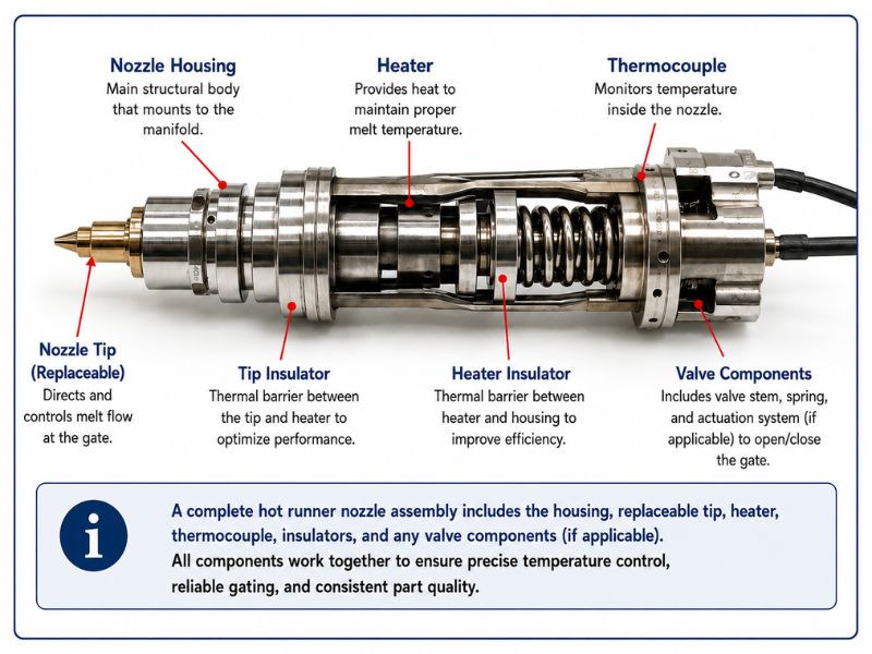
Table: Nozzle Components Breakdown
| Nozzle Components | Primary function | Common reason for replacement or service | Information needed for identification |
| Nozzle assembly | Carries and thermally controls melt from the manifold to the gate | Housing damage, extensive wear, incompatible architecture, multiple failed components or obsolete assembly | System family, drawing, part number, overall geometry, interfaces, electrical details, resin and symptoms |
| Nozzle body/Housing | Provides the structural body and melt-channel support; may carry or interface with the heater and thermocouple | Wear, distortion, damaged threads or interfaces, leakage, poor heater fit or obsolete geometry | Part number, length, diameters, interface details, material and surrounding components |
| Nozzle tip | Defines the final melt outlet and its relationship to the gate | Wear, erosion, damage, contamination, changed gate behavior or incompatibility | Outlet geometry, hole count, dimensions, material, sealing features and system family |
| Nozzle Heater | Supplies thermal energy to the nozzle zone | Open circuit, damaged leads, poor thermal contact, wrong rating, unstable or slow zone response | Style, dimensions, voltage, wattage, heated length, lead exit and termination |
| Thermocouple | Provides temperature feedback from its sensing location | Damage, unstable feedback, wrong type, incorrect location or connector mismatch | Type, dimensions, junction/installation style, polarity, lead and connector |
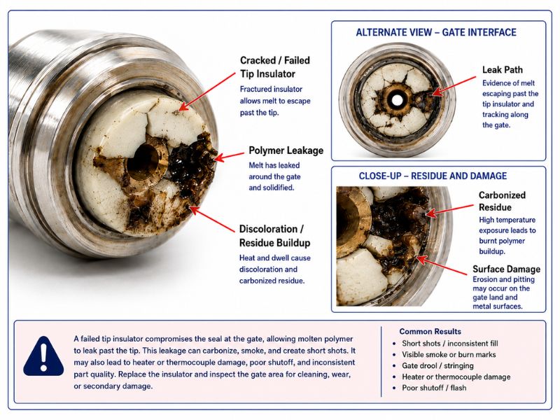
| Tip insulator | Controls heat transfer and/or supports the gate-region thermal relationship in designs that use one | Damage, compression, contamination, fitment mismatch or changed gate behavior | Material, geometry, thickness, system and tip relationship |
| Valve pin | Mechanically opens and closes the gate | Tip wear, bending, coating damage, sticking, inconsistent shutoff or alignment problems | Length, diameter, tip geometry, coating, actuation and gate details |
| Valve bushing | Guides or seals around the valve pin depending on design | Wear, leakage, pin misalignment, sticking or damaged interface | Dimensions, guidance/sealing design, pin and housing relationship |
| Gate insert | Provides the mold-side gate geometry and interface | Gate wear, cracking, damage, changed vestige or mismatch with the tip/pin | Gate design, mold drawing, material, dimensions and nozzle relationship |
| Seal component | Maintains containment, positioning or sealing at a defined interface | Leakage, flattening, heat damage, wear or incorrect stack-up | Material, profile, size, interface location and system specification |
Types of Hot Runner Nozzles
Hot runner manufacturers do not all classify nozzles in exactly the same way. Some organize products by gate-control method, while others also distinguish threaded, sliding, single-drop, manifold-mounted, side-gate, sprue-gate or application-specific families. The following categories describe common decision paths rather than a universal naming system.
Open-Gate/Open-Tip Nozzles
An open-gate nozzle has no valve pin mechanically closing the gate. Melt delivery and gate freeze-off are controlled by the nozzle-tip, gate and thermal relationship, together with the molding cycle and resin behavior.
Potential strengths include fewer moving components, relatively simple construction and fewer valve-actuation parts to service. Open configurations may be evaluated where the part, resin, gate appearance and process can tolerate thermally controlled shutoff.
Potential limitations include greater sensitivity to gate-region temperature, resin viscosity, pressure, decompression and the timing of natural freeze-off. Depending on the design and process, drooling, stringing, gate vestige or startup variation may require attention. An open nozzle should not be described as universally “high flow” or automatically appropriate for fast cycles; its actual capability depends on the melt path, gate, resin, part and complete system design.
Thermal-Gate or Hot-Tip Configurations
“Thermal gate,” “hot tip” and related terms may overlap with open-gate terminology, but manufacturers use them differently. In general, these configurations rely on controlled heat transfer near the gate and the formation of a temporary frozen layer or plug rather than a mechanical valve pin.
They can offer a compact gate-control method with no moving pin at the gate. Their performance depends strongly on the tip design, tip position, gate steel, insulation, local cooling, resin and temperature control. Small differences in geometry or heat transfer can change gate appearance, freeze-off, stringing, drooling or filling behavior.
A thermal-gate configuration should therefore be evaluated against the resin’s processing window and residence-time sensitivity, the acceptable gate mark, cavity consistency requirements and the mold’s ability to maintain the intended thermal relationship. It should not be presented as the automatic choice for every heat-sensitive resin.
Valve-Gate Nozzles
A valve-gate nozzle uses a pin or stem to mechanically open and close the gate. Depending on the system, actuation may be pneumatic, hydraulic or electric, and multiple gates may be operated together or controlled sequentially.
Valve gating can provide controlled shutoff, repeatable gate timing and the potential for a smaller or more controlled gate vestige. It can also support sequential filling, weld-line management and large or complex parts where the opening sequence affects appearance or packing.
The tradeoff is added mechanical and control complexity. The nozzle must be evaluated with the valve pin, bushing, actuator, seals, alignment, gate insert, cooling and controller. Pin wear, guidance, contamination, actuation variation or gate damage can create symptoms even when the nozzle body and heater remain serviceable. Valve gating is not automatically better; it is appropriate when its control benefits justify its cost, space, service and maintenance requirements.
Sprue-Gate or Larger-Flow Configurations
Some nozzle families include sprue-gate, larger-bore or larger-flow options for applications that require a less restrictive melt path, a larger gate, sub-runner feed or a geometry different from a fine direct gate. Manufacturer terminology varies, and a “sprue” option may be available in both non-valved and valved forms.
These configurations may reduce restriction for higher shot weights, more viscous materials, longer flow paths or thicker sections, but they can create a larger gate or runner feature that affects appearance, post-molding handling and freeze-off. Selection must be based on the manufacturer’s application data, mold-flow analysis where appropriate, and the complete part and gate design.
Table: Hot Runner Nozzles Comparison, Gate Types
| Nozzle or gate-control type | Shutoff method | Typical gate-appearance potential | Thermal sensitivity | Mechanical complexity | Maintenance demand | Application considerations | Main limitation to evaluate |
| Open-gate/open-tip | Natural or thermally influenced freeze-off; no valve pin | Depends strongly on tip, gate, resin and process | Moderate to high near the gate | Lower | Lower mechanical demand; thermal condition still matters | Simpler applications, acceptable vestige, compatible resin and stable process window | Drool, stringing, vestige and freeze-off sensitivity |
| Thermal-gate/hot-tip | Controlled heat transfer and temporary frozen layer/plug | Can be good when geometry and thermal relationship are correct | High | Lower | Inspection of tip, insulation and thermal control | Compact gating without moving pin; application-specific gate design | Sensitivity to tip position, insulation, local cooling and material behavior |
| Valve-gate | Mechanical pin/stem closes the gate | Often selected for controlled or appearance-sensitive gates | Thermal control remains important but shutoff is mechanical | Higher | Pin, bushing, actuator, seals, alignment and controller add service points | Controlled shutoff, sequential filling, demanding cosmetic or dimensional requirements | Cost, space, actuation and maintenance complexity |
| Sprue/larger-flow configuration | Thermal or mechanical depending on family | Usually larger gate/runner feature | Application-specific | Varies | Varies | Higher flow demand, more viscous resin, large parts or sub-runner feed | Larger gate, freeze-off and post-molding handling |
Final selection depends on the exact nozzle family, resin grade, part, mold and operating requirements.
Selecting a Nozzle Replacement Based on Resin Type
Resin behavior is one of the first selection filters because the nozzle changes how long the material remains hot, how much restriction it encounters and how consistently the gate region is controlled. Use the resin supplier’s grade-specific processing guidance and the hot runner manufacturer’s application recommendations; broad material-family labels are not sufficient.
| Resin characteristic | Why it matters | Nozzle factors to evaluate | Potential risk if mismatched |
| Narrow processing-temperature window | Small thermal variations may change viscosity or accelerate degradation | Thermal profile, heater placement, thermocouple location, heat loss and residence volume | Unstable fill, degradation, stringing, freeze-off or cosmetic variation |
| Heat sensitivity | Time at temperature can damage the resin even when the setpoint appears acceptable | Melt volume, dead spots, tip thermal relationship, startup/shutdown strategy and color-change behavior | Burned material, gas, black specks, loss of properties or deposits |
| Residence-time sensitivity | Large internal volume or stagnant regions can expose material for too long | Nozzle length, channel design, gate bubble/dead volume, shot size and cycle interruptions | Contamination, color streaking, degradation or difficult changeovers |
| High viscosity | More pressure may be required to move material through a restrictive path | Flow-bore size, nozzle length, tip geometry, gate restriction and available injection pressure | Short shots, hesitation, excessive pressure demand or imbalance |
| Low viscosity | Melt may be more prone to leakage or drool when shutoff is weak | Gate-control method, sealing, tip/gate relationship, decompression strategy and valve closure | Drooling, stringing, leakage or inconsistent gate behavior |
| Shear sensitivity | High velocity through restrictive geometry can generate heat and damage the material | Channel transitions, tip and gate restriction, fill speed, valve opening behavior | Discoloration, loss of properties, burns or surface defects |
| Moisture sensitivity | Moisture can create degradation and defects that resemble thermal or nozzle problems | Drying verification, residence time, contamination control and diagnosis process | Splay, gas, hydrolytic degradation, streaks or false nozzle diagnosis |
| Crystallinity and freeze behavior | Gate freeze and mold-temperature interaction affect packing and cycle behavior | Gate-control method, tip/gate thermal relationship, cooling and packing requirements | Premature freeze, poor packing, sink, dimensional variation or gate problems |
| Abrasive fillers | Glass, mineral, carbon or other fillers can accelerate wear at restrictions and moving interfaces | Tip/housing/pin material, coating, gate geometry, replaceable wear components and inspection access | Enlarged or eroded geometry, leakage, poor vestige or recurring wear |
| Corrosive resin or additives | Resin chemistry or decomposition products can attack materials and surfaces | Housing/tip/pin materials, coatings, sealing surfaces, purge/cleaning strategy and residence control | Pitting, contamination, leakage, seized components or shortened service life |
| Flame retardants and colorants | Additives can change viscosity, stability, plate-out and changeover behavior | Resin-specific guidance, surface finish, residence volume, dead spots and cleanability | Deposits, color contamination, pressure change or surface defects |
| Recycled-content variation | Lot-to-lot viscosity and contamination may be less consistent | Operating window, flow capacity, filtration/contamination risk and diagnostic data | Process variation, blockage, wear or inconsistent cavity balance |
| Frequent resin or color changes | Internal volume and stagnant regions affect changeover time and residue | Streamlined melt path, low dead volume, accessible/serviceable tips and cleaning compatibility | Long changeovers, streaks, black specks and repeated teardown |
A resin category alone does not determine whether the application should use an open, thermal or valve-gated nozzle. The correct decision combines grade-specific material behavior with the part, gate, flow path, cycle and maintenance strategy.
Selecting a Nozzle Replacement Based on the Part and Gate
The nozzle and gate should be evaluated as one system. A nozzle can have enough flow capacity on paper and still be inappropriate if its tip geometry, gate-control method, vestige, thermal relationship or mold-side interface conflicts with the part.
Part size, weight and flow distance
Larger shots, longer flow paths and difficult filling patterns may require a less restrictive melt path or multiple gates. Very small parts or tight-pitch cavity layouts may prioritize compact nozzles and precise local thermal control. Neither situation can be solved from shot weight alone; wall thickness, resin viscosity, fill time, pressure, runner layout and cavity count also matter.
Wall thickness and filling speed
Thin walls can require high flow rates and fast filling, increasing sensitivity to pressure drop and shear at the nozzle and gate. Thick sections may require sustained packing and a gate that remains effective long enough to meet dimensional or sink requirements. The nozzle architecture must support the required fill and pack behavior without creating an unnecessarily restrictive or poorly controlled gate.
Cosmetic surface and gate vestige
For visible Class-A or appearance-sensitive surfaces, the gate mark, blush, halo, stringing and flow-front behavior may drive the decision. Valve gating may be considered when mechanical shutoff and gate control provide a meaningful benefit, but tip/pin alignment, gate steel, cooling, opening behavior and resin remain important. Thermal gating can also produce acceptable results when the application is designed around it.
Gate location and accessibility
The gate may be positioned on a visible face, rib, boss, edge, underside or sidewall. Available steel, cooling, ejection, cavity spacing and service access can limit the nozzle and tip style. A side-gate or specialized nozzle may be necessary when direct axial access is unavailable, but the choice must follow the specific manufacturer’s design and mold requirements.
Weld lines, sequential filling and packing
Large, long or complex parts may use multiple valve gates to control where melt fronts meet and how the cavity packs. Sequential valve gating can move weld lines or control fill progression, but it adds timing, sensing, actuation and process-development requirements. The nozzle decision should be validated with mold-flow analysis or system-manufacturer engineering when these outcomes are critical.
Post-molding gate treatment and automation
An open or sprue-style gate may create a feature that requires trimming or sub-runner handling. A valve-gated direct gate may reduce or eliminate secondary de-gating, but it increases system complexity. The best lifecycle choice depends on production volume, cosmetic standards, automation, maintenance capability and downtime risk.
Selecting a Nozzle Replacement Based on Flow, Pressure and Shear
The nozzle is a pressure-consuming section of the melt-delivery path. Its length, internal channel, transitions, tip geometry and gate restriction interact with resin viscosity, temperature and fill speed. Selection should therefore be evaluated as part of the full machine-to-cavity pressure and shear budget.
- Nozzle length: A longer flow path generally increases resistance and residence volume, but the effect depends on channel size, transitions and resin.
- Melt-channel size: A smaller channel may reduce internal volume but increase pressure demand and shear. A larger channel may reduce restriction while increasing residence volume and the amount of material retained during a changeover.
- Tip geometry: Outlet count, outlet orientation, land, transitions and the relationship to the gate affect local velocity, heat transfer and pressure loss.
- Gate restriction: A small or poorly matched gate can become the dominant restriction even when the nozzle body is adequately sized.
- Fill speed: Higher velocity can increase pressure and shear heating through restrictive regions.
- Temperature: Raising temperature can reduce viscosity for many materials, but it is not a universal correction and may increase degradation, drool or residence-time risk.
- Cavity balance: One restrictive, contaminated or thermally unstable nozzle can create cavity-to-cavity variation even when the manifold was designed to be balanced.
An undersized or excessively restrictive path may contribute to high pressure demand, hesitation, short shots, shear heating or imbalance. An oversized path or gate may create different problems, including larger residence volume, weaker freeze-off, drool, excessive vestige or less controlled packing. There is no universal nozzle-sizing formula that replaces resin data, mold-flow analysis, manufacturer selection tools and qualified engineering review.
Selecting a Nozzle Replacement Based on Mold Architecture
Dimensional compatibility includes much more than overall nozzle length and outside diameter. The nozzle must operate correctly when the mold heats, expands, closes, opens and transfers pressure through the surrounding stack.
Evaluate the following:
- Cavity count, drop location and cavity spacing.
- Manifold layout and nozzle-to-manifold interface.
- Threaded, sliding, seated or other manufacturer-specific nozzle attachment.
- Available mold thickness and nozzle length.
- Bore, cutout, counterbore, support and clearance geometry.
- Nozzle-to-gate alignment and the relationship to the gate insert.
- Cold and operating stack height.
- Thermal expansion of the manifold, nozzle and support structure.
- Sealing faces, contact pressure and backup/support conditions.
- Space for heaters, thermocouples, leads, connectors and valve actuation.
- Mold cooling near the gate and heat loss into surrounding plates.
- Access for tip, heater, thermocouple, pin or complete-nozzle replacement.
- Whether the hot half must be removed for routine service.
- Available independent temperature-control zones.
- Controller and wiring-harness compatibility.
A nozzle that fits the cold mold may still be incorrect if its operating expansion, stack height, sealing relationship or gate position differs from the original design. Incorrect fitment can cause leakage, component loading, poor thermal contact, pin misalignment or damage to the mold and hot runner.
Heater and Thermocouple Selection Within the Nozzle Assembly
The heater and thermocouple are part of the nozzle’s selection and compatibility. A replacement should match the original design or an engineering-approved alternative.
Heater factors to verify
- Heater style, including coil, band, cartridge, brazed, cast-in or other system-specific construction.
- Voltage and wattage.
- Watt density and how heat is distributed along the nozzle.
- Inside/outside diameter and fit against the heated surface or bore.
- Heated length and intentional cold sections.
- Lead exit position, lead length and protective construction.
- Connector, plug or terminal style.
- Grounding and electrical-safety requirements.
- Thermal contact, installation method and replaceability.
- Controller output and zone compatibility.
Heater performance depends on operating temperature, watt density, fit, thermal contact and termination environment together. A heater with the same voltage and wattage can still be unsuitable if its dimensions, heated profile, lead arrangement or heat-transfer relationship differ.
Thermocouple factors to verify
- Thermocouple type and polarity.
- Probe or wire construction.
- Sensing-junction location relative to the steel and heater.
- Grounded, ungrounded or system-specific configuration.
- Diameter, length, bend, bayonet, ring, washer or other mounting style.
- Lead material, insulation, length and routing.
- Connector and controller compatibility.
- Electrical-noise and grounding environment.
A grounded junction may respond faster, while an ungrounded junction can provide electrical isolation and reduce ground-loop noise. The correct choice depends on the original system, controller and measurement environment; it should not be changed casually during replacement.
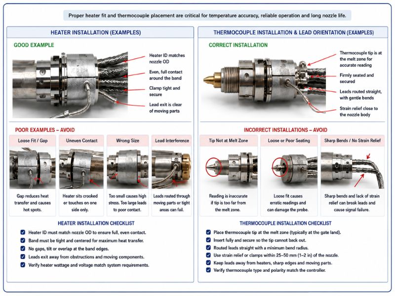
For Heater or Thermocouple Replacements, visit PCT Nozzle Heaters and Thermocouples product information pages.
Nozzle Tip Selection Within the Complete Assembly
The nozzle tip is the final flow and thermal interface before the gate, but it must be selected as part of the complete assembly. Relevant variables may include:
- Outlet geometry and number of holes.
- Outlet diameter and orientation.
- Overall length, body diameter and seating depth.
- Thread or retention details.
- Sealing faces and interface geometry.
- Relationship to the gate insert, insulator and mold steel.
- Material, hardness, coating and surface finish.
- Thermal conductivity and heat-retention behavior.
- Wear and corrosion resistance.
- Resin, filler and color-change compatibility.
- Open, thermal or valve-gate design.
- System-family and nozzle-housing fitment.
A larger outlet is not automatically better, and a smaller outlet is not automatically more precise. The correct geometry balances pressure, shear, gate behavior, residence volume, freeze-off, appearance and the original manufacturer’s thermal design.
For Nozzle Tip and Insulator Replacements, visit PCT Nozzle Tips and Insulators product information pages.
Common Nozzle Materials, Coatings and Wear Resistance
Material selection should be evaluated by component and location. The best material for a tip is not necessarily the best material for a housing, valve pin, bushing or gate insert. The original design may intentionally combine high-strength, wear-resistant, corrosion-resistant, low-conductivity and high-conductivity materials to produce the required thermal and mechanical behavior.
Important considerations include:
- Thermal conductivity and how quickly heat moves toward or away from the gate.
- Strength and dimensional stability at operating temperature.
- Resistance to thermal cycling and mechanical loading.
- Wear from glass, mineral, carbon or other fillers.
- Corrosion from resin chemistry, additives or degradation products.
- Galling or sliding wear at valve pins and bushings.
- Durability of sealing and seating surfaces.
- Coating compatibility with the base material and operating environment.
- Surface finish, material hang-up and cleanability.
- Ability to inspect, refurbish or replace the wear component.
- Availability of an exact compatible part for the system family.
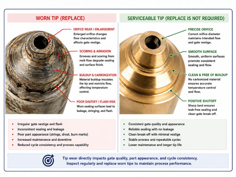
Do not assume that a harder material, more conductive alloy or low-friction coating is universally superior. Changing a material can alter heat transfer, expansion, fit, surface interaction and service behavior. Follow the OEM design or use a qualified replacement engineered for the exact assembly and resin.
For Nozzle Housing Replacements, visit PCT Nozzle Housings product information page.
Selecting Open-Gate Versus Valve-Gate Nozzles
Open and valve-gated nozzles solve different application problems. The decision should be made from gate control, part quality, process, mold and lifecycle requirements rather than a belief that one is universally more advanced.
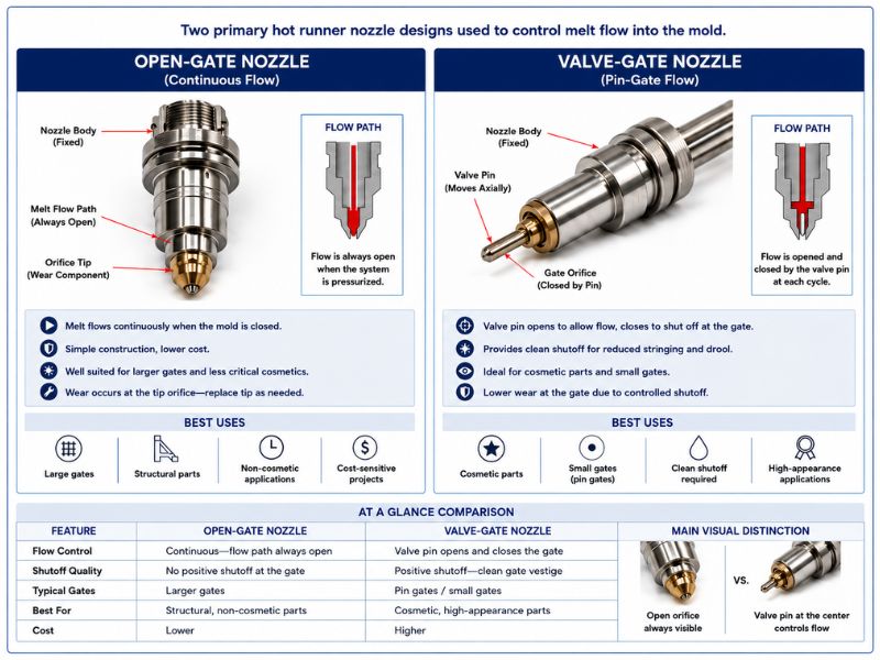
| Decision factor | Thermal & Open configuration | Valve configuration |
| Gate shutoff | Relies on thermal behavior and freeze-off | Uses a mechanically actuated pin or stem |
| Gate appearance | Can be acceptable to excellent when the tip, gate and process are correctly designed | Often selected when controlled gate vestige or repeatable shutoff is important |
| Drooling/stringing | May be more sensitive to local heat, viscosity, pressure and decompression | Can reduce thermally driven shutoff variation, but pin/gate wear or timing can still cause defects |
| Gate vestige | Depends on thermal gate design, tip position, resin and process | Can provide controlled vestige; exact result depends on pin/gate geometry and alignment |
| Sequential filling | Not mechanically sequenced at individual gates | Supports sequential or individually controlled opening in suitable systems |
| Actuation | None at the gate | Pneumatic, hydraulic or electric, depending on system |
| Mold space | Generally fewer actuation components | Requires room for pins, bushings, actuators, plates, lines or motors |
| Maintenance | Fewer moving parts; tip, insulation and thermal condition remain important | Adds pin, bushing, actuator, seals, guidance and control maintenance |
| Initial system cost | Often lower for a comparable simple application | Generally higher because of added components and controls |
| Process development | Focus on thermal gate behavior and freeze-off | Includes thermal control plus pin opening/closing, speed and sequence |
| Best evaluation question | Can the resin, gate and part meet requirements with thermally controlled shutoff? | Do controlled shutoff, vestige, sequencing or packing benefits justify the added complexity? |
A valve gate may be favored for appearance-sensitive parts, sequential filling, controlled gate closure or process repeatability. An open or thermal gate may be favored where a simpler architecture meets the part and resin requirements. Final selection should be confirmed through the system manufacturer, mold designer and application engineering process.
Replacement-Nozzle Compatibility: What Must Match?
Replacement-nozzle identification is one of the highest-risk points in the buying process because similar-looking parts are not necessarily interchangeable. Compatibility may require matching all of the following:
- Manufacturer or system family used for identification.
- Mold, tool, hot half or project number.
- Existing nozzle, assembly or component part number.
- Assembly drawing and revision.
- Nozzle attachment method and manifold interface.
- Overall length and operating stack relationship.
- Body diameters, shoulders, seats and support geometry.
- Melt-channel diameter, transitions and inlet/outlet relationship.
- Sealing faces and required contact locations.
- Tip geometry, outlet pattern, gate relationship and retention method.
- Thread form, pitch, length and orientation where applicable.
- Heater style, dimensions, voltage, wattage and heated profile.
- Thermocouple type, installation, polarity, lead and connector.
- Lead exit, routing and harness connection.
- Valve-pin length, diameter, tip, coating and actuation relationship.
- Valve-bushing, piston, seal and spacer details where applicable.
- Gate insert and mold-side geometry.
- Cold and operating stack height.
- Component materials, coatings and surface treatments.
- Thermal-expansion and support requirements.
- Resin grade, fillers, operating conditions and production symptoms.
A replacement that matches only the overall length and outside diameter can still be wrong. Changes in the melt path, sealing surface, heater profile, tip position, valve-pin relationship or thermal expansion may cause leakage, poor gate behavior, component damage or process instability.
What Information Should Be Sent When Requesting Replacement Nozzle Components?
A complete request helps the supplier determine whether the reader needs a full nozzle, housing, tip, heater, thermocouple, insulator, valve component or service evaluation.
- OEM or hot runner system manufacturer for identification.
- System family, mold number, tool number and hot-half identification.
- Existing component and assembly part numbers.
- Nozzle and hot-runner drawings, including revision where available.
- Clear photographs of the complete assembly and identifying marks.
- Critical dimensions taken from the drawing or a controlled inspection.
- Resin manufacturer, grade, additives and fillers.
- Number of cavities and affected positions.
- Heater voltage, wattage, dimensions, lead exit and connector.
- Thermocouple type, installation and termination details.
- Valve-gate, pin, bushing and actuation information.
- Reason for replacement and whether performance changed over time.
- Current production symptoms, affected cavities and process history.
- A sample component when reverse engineering is required and shipment is appropriate.
Do not rely on a photograph alone when exact dimensions, internal geometry or electrical details determine compatibility.
Common Hot Runner Nozzle Problems
Nozzle-related symptoms should be treated as diagnostic clues, not automatic proof that the complete nozzle must be replaced. Several causes can exist at the same time.
Gate-Area Symptoms
- Drooling or material leaking from an open gate.
- Stringing or angel-hair formation.
- Excessive or inconsistent gate vestige.
- Premature gate freeze or delayed freeze-off.
- Gate blush, halo, clouding or flow marks.
- Valve-pin witness marks or inconsistent shutoff.
- Leakage near the tip, gate insert or interface.
Possible contributors include the gate-control method, tip condition, tip/gate position, local heat transfer, insulation, resin viscosity, valve-pin closure, gate wear, pressure, decompression or cycle conditions.
Filling and Flow Symptoms
- Short shots or incomplete fill.
- Hesitation at one or more gates.
- Cavity-to-cavity variation.
- Increased injection-pressure demand.
- Uneven filling or part-weight variation.
- Restriction that appears isolated to one drop.
Possible contributors include an undersized or contaminated flow path, damaged tip, cold or unstable nozzle zone, incorrect thermocouple feedback, gate restriction, valve-pin position, manifold imbalance, machine pressure limits, material variation or venting.
Material-Quality Symptoms
- Black specks or burned particles.
- Burned or degraded material.
- Color contamination or slow color change.
- Streaking or discoloration near one gate.
- Resin degradation after pauses or startup.
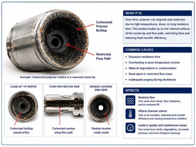
Possible contributors include excessive time at temperature, dead spots, carbonized residue, unstable heating, a damaged thermocouple, contamination, incompatible materials, moisture, shear, venting or upstream manifold conditions.
Thermal and Electrical Symptoms
- Slow heat-up or slow recovery.
- Temperature overshoot or oscillation.
- A zone that does not reach or hold setpoint.
- Cold spots or intermittent gate behavior.
- Heater alarms, open circuits or ground faults.
- Thermocouple drift, reversed polarity or incorrect feedback.
- Damaged leads, connectors or wiring harnesses.
The problem may involve the heater, thermocouple, fit and thermal contact, lead damage, controller tuning, power output, wiring, grounding, insulation or heat loss into the mold.
Mechanical Symptoms
- Leakage at the manifold/nozzle or nozzle/gate interface.
- Worn, cracked, distorted or damaged housing.
- Tip erosion, pitting or damaged threads.
- Valve-pin or bushing wear.
- Sticking or inconsistent actuation.
- Misalignment or an incorrect stack relationship.
- Seal failure that returns after replacement.
These symptoms require inspection of the surrounding assembly, supports, spacers, sealing surfaces, thermal expansion and actuation.
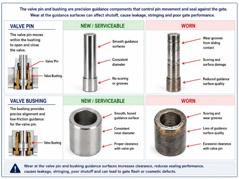
Table: Hot Runner Nozzle Troubleshooting
| Observed symptom | Possible nozzle-related cause | Other conditions that must be checked | Recommended inspection area | Possible next action |
| Drooling | Open/thermal gate cannot freeze consistently; tip damage; excessive local heat; poor valve closure | Resin viscosity, decompression, pressure, cycle interruption and controller behavior | Tip, gate insert, insulator, heater/TC, valve pin and process history | Verify process and resin guidance; inspect components; replace or repair only after cause is identified |
| Stringing | Tip/gate thermal mismatch, residue, worn tip or incomplete valve shutoff | Mold opening, decompression, resin, gate cooling and cycle | Tip, gate, insulation, pin/bushing and thermal zone | Inspect and clean if appropriate; verify fit and shutoff; replace worn components |
| Short shot at one cavity | Local restriction, cold nozzle zone, damaged tip, valve not fully open | Manifold balance, venting, machine pressure, material and cavity condition | Heater, TC, tip, pin, flow path and gate | Test the thermal zone; inspect restriction and valve motion; clean, repair or replace as evidence supports |
| Short shots across multiple cavities | Nozzle selection may be too restrictive, but a system-level issue is more likely | Machine, manifold, resin, temperature profile, shot size and venting | Full melt path and process data | Evaluate upstream system and process before replacing nozzles |
| Increased pressure demand | Restrictive tip/gate, buildup, wear deformation or undersized path | Resin lot/viscosity, temperature, machine and manifold | Tip, internal channel, gate and affected cavity data | Compare current pressure trend with baseline; inspect and clean; review original sizing if present from startup |
| Cavity-to-cavity variation | One nozzle zone, tip or valve differs from others | Manifold balance, cooling, cavity condition, venting and actuation | Compare zone data, tips, pins, gates and part weights by cavity | Identify the outlier; inspect the full drop rather than replacing all nozzles |
| Black specks near one gate | Carbonized residue or local overheating in tip/nozzle | Manifold contamination, residence time, resin moisture, startup/shutdown and shear | Tip, flow path, heater/TC and upstream branch | Follow safe cleaning/inspection guidance; correct the degradation cause; replace damaged parts |
| Burn marks | Shear or degradation near the gate may be involved | Trapped air, venting, fill speed, resin, residence time and machine settings | Tip/gate restriction, venting and thermal history | Diagnose air versus material degradation before altering hardware |
| Unstable temperature | Poor heater contact, damaged heater, incorrect TC feedback or heat loss | Controller output, wiring, connector, grounding and nearby cooling | Heater, TC, leads, insulation and controller zone | Test according to OEM/plant procedures; repair wiring or replace the confirmed failed component |
| Leakage at nozzle interface | Damaged sealing face, housing, seal or incorrect stack height | Thermal expansion, supports, manifold alignment and assembly procedure | Nozzle/manifold interfaces, spacers, seals and contact surfaces | Stop operation as required; disassemble safely; inspect the complete stack and repair damaged interfaces |
| Poor valve-gate vestige | Pin/gate wear, misalignment, incomplete stroke or contaminated gate | Actuation pressure, sequence, cooling, resin and gate insert | Pin, bushing, actuator, gate insert and nozzle alignment | Verify actuation and inspect wear; replace or rebuild the affected components |
| Slow color change | Retained material in tip/nozzle, dead volume or surface deposits | Manifold design, resin compatibility, purge method and shot utilization | Tip, nozzle path and upstream flow channels | Follow resin/OEM changeover guidance; clean or service only where residue is confirmed |
For broader symptom-based inspection priorities, use PCT’s Hot Runner Troubleshooting Assistant.
Was the Nozzle Replacement Incorrectly Selected, or Has It Deteriorated?
The timing and pattern of the problem often help separate an original design mismatch from a component that deteriorated later.
Selection or Design Mismatch
Possible indicators include:
- The problem was present at initial mold startup or from the first use of a new resin or part design.
- Pressure demand, shear or fill limitations are consistent and repeatable.
- Gate-quality problems remain despite stable components and validated processing.
- The resin is incompatible with the original thermal, wear or residence-time design.
- The flow path cannot support the required fill or packing behavior.
- The gate-control method cannot meet the part’s appearance or sequence requirements.
- The mold lacks enough thermal control or service access for the selected architecture.
A design mismatch usually requires application review rather than repeated component replacement.
Fitment or Installation Problem
Possible indicators include:
- Leakage begins after assembly, service or component replacement.
- Tip position, gate alignment or valve-pin movement is incorrect.
- The cold or operating stack relationship does not match the drawing.
- The heater or thermocouple is connected to the wrong zone or has the wrong type/rating.
- A sealing face, thread or interface was damaged during installation.
- A visually similar but incompatible component was installed.
Fitment problems can damage otherwise serviceable parts, so the complete interface should be checked before another replacement is installed.
Wear, Contamination or Component Failure
Possible indicators include:
- The mold previously ran acceptably and performance degraded over time.
- One cavity or position changes before the others.
- Tip, gate, pin or bushing wear is visible or measurable against the drawing.
- Carbon buildup, color residue or degraded material is present.
- Heater response changes, a zone recovers slowly or a thermocouple becomes unstable.
- Insulation, seals, leads or connectors show damage.
- Valve motion becomes inconsistent or leakage appears after extended service.
These conditions may be resolved through cleaning, component replacement, repair or rebuilding if the underlying geometry remains serviceable.
Processing or Material Problem
Possible indicators include:
- Symptoms follow a resin lot, color, recycled-content level or drying problem.
- Material moisture, contamination or degradation is confirmed.
- The temperature profile, fill speed, pressure, hold or decompression changed.
- The machine cannot provide the required pressure or control.
- Venting or cavity conditions cause defects that appear to originate at the gate.
- The same issue appears across multiple nozzles simultaneously.
Processing and hardware causes can overlap. A restrictive or worn nozzle may become visible only after a resin or process change, while a material problem can expose a nozzle design with little operating margin.
Nozzle Cleaning, Maintenance and Inspection
Nozzle maintenance should be condition-based and supported by OEM instructions, process history and observed wear – not a universal cycle count. At a high level, inspection may include:
- Tip outlet, sealing geometry, gate relationship and visible wear.
- Accessible melt path for contamination, carbon, residue or damage.
- Heater dimensions, thermal contact, leads and electrical condition.
- Thermocouple installation, polarity, leads, connectors and feedback stability.
- Tip insulator condition, fit and contamination.
- Valve pin, bushing, actuator, seals and gate insert where applicable.
- Nozzle housing, threads, seats, sealing faces and signs of leakage.
- Alignment, spacers, support conditions and stack relationship.
- Comparison of affected versus stable cavities or zones.
- Maintenance and production records for repeated position-specific failures.
Aggressive scraping, drilling, grinding, open-flame heating or uncontrolled chemical exposure can damage precision flow, sealing and gate surfaces. Maintenance and disassembly should be performed by trained personnel using the system drawing, OEM procedure and plant safety requirements.
Looking for Cleaning & Maintenance Assistance? View our Hot Runner Cleaning or Hot Runner Maintenance service pages for more information.
Repair, Rebuild or Replace the Nozzle?
The correct action depends on which component failed, whether the critical geometry remains serviceable and whether the original nozzle is still appropriate for the application.
A Component Replacement May Be Appropriate When
- The nozzle body and critical interfaces remain serviceable.
- The problem is isolated to a replaceable tip, heater, thermocouple, insulator, seal, valve pin or bushing.
- The original part can be identified and compatibility confirmed.
- The surrounding cause – such as misalignment, poor thermal contact or contamination – has been addressed.
Nozzle Repair or Rebuilding May Be Appropriate When
- Multiple serviceable components require coordinated repair or replacement.
- Heater or power leads require professional repair.
- The assembly needs cleaning, dimensional inspection and electrical evaluation.
- Sealing, fitment or alignment must be evaluated before reassembly.
- The complete nozzle can be restored without changing its original application geometry.
- An obsolete component may be supported through verified reverse engineering.
Complete Nozzle Replacement May Be Appropriate When
- The housing is cracked, severely worn, distorted or damaged at a critical interface.
- Melt-channel, sealing, thread, tip-seat or gate-related geometry cannot be restored.
- The assembly is incomplete or repeatedly fails because replacement components cannot be matched reliably.
- The application now requires a different flow capacity, gate-control method, material capability or service strategy.
- Repair is technically impractical or would not restore reliable compatibility.
Further System Evaluation May Be Required When
- Multiple nozzles show the same symptom.
- The cause may be in the manifold, controller, wiring harness or machine.
- Leakage suggests a stack-height, support, alignment or thermal-expansion issue.
- Electrical instability crosses several zones.
- The resin or processing conditions are outside the validated operating range.
- The same component fails repeatedly in the same position.
Do not make the repair-versus-replace decision from component price alone. Consider downtime risk, part availability, future serviceability, documentation, remaining mold life and whether the root cause has been corrected.
When to Consider a Nozzle Upgrade
An upgrade should address a verified application limitation rather than serve as a generic performance promise. It may be appropriate when:
- The mold will process a different resin, additive package or filler level.
- Abrasive or corrosive conditions exceed the original component capability.
- New cosmetic, vestige, weld-line or sequential-filling requirements cannot be met by the current gate-control method.
- Repeated heater, tip, pin or seal failures are linked to a known fitment or thermal limitation.
- Original parts are obsolete or no longer supportable.
- The design prevents practical heater, thermocouple, tip or valve-component service.
- A custom replacement can preserve the mold while correcting a documented compatibility issue.
- A complete application review supports conversion to a different nozzle or gate architecture.
Looking to Upgrade Your Hot Runner System? Learn More About PCT Hot Runner Services.
Select and Support the Nozzle as a Complete Application System
Successful hot runner nozzle selection requires matching the resin, part, gate, flow, pressure, shear, thermal control, mold geometry, operating stack, wear conditions, service access and lifecycle requirements. The nozzle should be evaluated with the manifold, gate insert, heater, thermocouple, tip, insulation, valve components, seals, controller and processing conditions; Not as an isolated shape or catalog item.
An apparent nozzle problem may be limited to a replaceable component, or it may point to contamination, an electrical issue, fitment, valve wear, sealing, the manifold, the resin or the process. A qualified inspection helps separate adjustment or cleaning from component replacement, rebuilding, complete-nozzle replacement or system-level service.
Polymer Cleaning Technology supports aftermarket-compatible hot runner components and system services, including nozzle tips, housings, heaters, thermocouples, insulators, valve pins, valve bushings, seals, complete nozzle evaluation, repair, rebuilding, cleaning, maintenance, custom parts and reverse engineering.
To request technical support or a quote, submit the OEM or system family, mold/tool number, existing part number, drawings, photographs, critical dimensions, resin and additives, electrical information, valve-gate details, production symptoms and the desired replacement or repair outcome.
Polymer Cleaning Technology: Leading the Way in Hot Runner Parts and Services
With a reputation for precision and reliability, PCT helps manufacturers keep their hot runner systems operating at peak performance.
Services Offered
Hot Runner Cleaning
Specialized chemical-free cleaning systems remove polymer residue without damaging metal surfaces.
Hot Runner Maintenance
Thorough Inspection, Testing, Analysis, Assembly, and Comprehensive Reports.
Preventive Maintenance Programs
Tailored service schedules to suit production environments.
Component Repair & Refurbishment
Includes manifolds, heaters, nozzles, and temperature control systems.
Reverse Engineering & Custom Parts
Solutions for hard-to-find or discontinued OEM parts.
Parts Inventory
- Nozzle Tip Insulators
- Heaters (coils, bands, cartridges)
- Thermocouples
- Nozzle Tips
- Valve Pins
- Nozzle Housings
- Valve Bushings
- Pistons & Spacers
- Seal kits (O-Rings)
Related Reading
- Hot Runner Components: A Complete Overview
- Troubleshooting Defects Caused by Nozzle Tip Insulation
- A Brief Guide to Hot Runner Manifold Cleaning & Maintenance
*This information is to be used as a general guideline only. Speak to your system manufacturer directly for verified information regarding your Hot Runner System.
*Note: Some analysis and conclusions in this article are based on available data, industry documentation, and observed shop-floor trends. Where specific values or figures are not published, reasonable assumptions have been made to illustrate common maintenance scenarios.

Find this information useful? Share with friends & colleagues:
Contact Information:
Polymer Cleaning Technology, Inc.
sales@polymercleaning.com
+1 (908) 281-0055

