How hole count, outlet size, geometry, material, and OEM-compatible fitment influence nozzle tip selection and performance.
Hot runner nozzle tips may be small compared to the manifold, nozzle body, or overall hot half, but they play one of the most important roles in the system. They are the final point where molten polymer exits the nozzle and enters the gate area, which means nozzle tip designs directly influences melt flow, pressure drop, gate behavior, part consistency, and long-term maintenance demands.
Different nozzle tip configurations are used for different molding conditions, gate styles, resin types, cavity layouts, and OEM system families. Two tips may appear similar at a glance, but small differences in outlet count, outlet size, overall length, body diameter, sealing geometry, or wear material can lead to very different results in production.
For molders, technicians, and buyers sourcing replacement hot runner parts, understanding these differences helps answer three practical questions:
- what this nozzle tip style is designed to do
- where it is typically used
- what must be matched to replace it correctly
In this guide, we’ll review 10 common hot runner nozzle tip configurations, what each is generally used for, and the fitment variables that matter when sourcing replacement parts for systems compatible with leading OEM hot runner platforms.
As with the rest of our hot runner replacement part content, OEM names are used for identification and compatibility purposes only.
Contact +1 (908) 281-0055 or sales@polymercleaning.com to discuss your Hot Runner Systems today! Experts in High Quality Hot Runner Parts, Repair, & Maintenance for all OEM.
Nozzle Tip Configurations Explained
The nozzle tip sits at one of the most sensitive points in the entire hot runner assembly. It affects how molten resin enters the cavity, how heat is retained at the gate, how the gate seals between shots, and how consistently cavities fill over long production runs.
A poorly matched nozzle tip can contribute to issues such as:
- stringing
- drool
- poor gate vestige
- inconsistent cavity filling
- leakage at the tip interface
- accelerated wear
- unstable thermal behavior near the gate
That is why nozzle tip replacement should never be treated as a simple visual match. In practice, correct replacement depends on geometry, fitment, thermal behavior, sealing surfaces, and system compatibility.
The Main Variables That Differentiate Nozzle Tip Designs
Before looking at specific configurations, it helps to understand the variables that separate one nozzle tip design from another.
Outlet count
Some nozzle tips use a single melt outlet, while others use multiple outlets. The number of outlets changes how melt is delivered into the gate region and how flow is distributed at the end of the nozzle.
Outlet size
Orifice diameter influences pressure drop, shear, filling speed, and gate behavior. A small difference in hole diameter can noticeably change molding performance.
Tip geometry
The shape of the tip end affects how melt exits, how the gate seals, and how the tip interfaces with surrounding steel.
Overall length and body diameter
These are critical fitment dimensions. Even when the style appears correct, incorrect length or diameter can create assembly issues, leakage, poor seating, or unwanted thermal behavior.
Sealing design
Some nozzle tips rely on specific sealing surfaces or integrated sealing features. These details must be preserved in replacement parts.
Material and wear surface
Material selection matters. Depending on the application, nozzle tips may be produced from hardened tool steels and other wear-focused materials or surface treatments chosen for durability, temperature resistance, and service life.
OEM / system-family compatibility
We manufacture replacement nozzle tips for compatibility with a wide range of major OEM hot runner system families, but nozzle-tip replacement should still be approached as an exact compatibility and fitment process rather than a generic universal swap.
Quick Comparison Table
| Nozzle Tip Designs | What It Is Commonly Used For | Key Variables to Match | Common Compatibility Context |
|---|---|---|---|
| Single-hole tip | Standard direct melt delivery | outlet diameter, total length, body diameter | Common across many OEM-compatible system families |
| Multi-hole tip | Controlled melt distribution near the gate | hole count, spacing, outlet size | More specialized or geometry-specific assemblies |
| Small-orifice tip | Fine flow control and tighter gate behavior | orifice diameter, resin sensitivity | Appearance-sensitive or precision-gate applications |
| Large-orifice tip | Higher flow volume with less restriction | outlet size, sealing behavior | Higher-throughput or less restrictive flow needs |
| Extended-length tip | Deeper-reach or length-specific gate interfaces | total length, seating geometry | OEM/system-specific stack-up requirements |
| Large-body / heavy-duty tip | Larger assembly platforms or more robust tip designs | body diameter, interface geometry | Larger nozzle platforms and demanding production conditions |
| Swaged tip | Mechanically integrated tip/body designs | construction style, dimensions, outlet pattern | Certain PET, packaging, or OEM-defined assemblies |
| Seal-integrated tip | Designs where tip geometry contributes to sealing | sealing surfaces, fit, material | Leakage-sensitive assemblies |
| Wear-resistant tip | Abrasive materials or long-run durability | base material, wear surface, geometry | Filled materials or high-volume environments |
A Closer Look at Common Nozzle Tip Designs
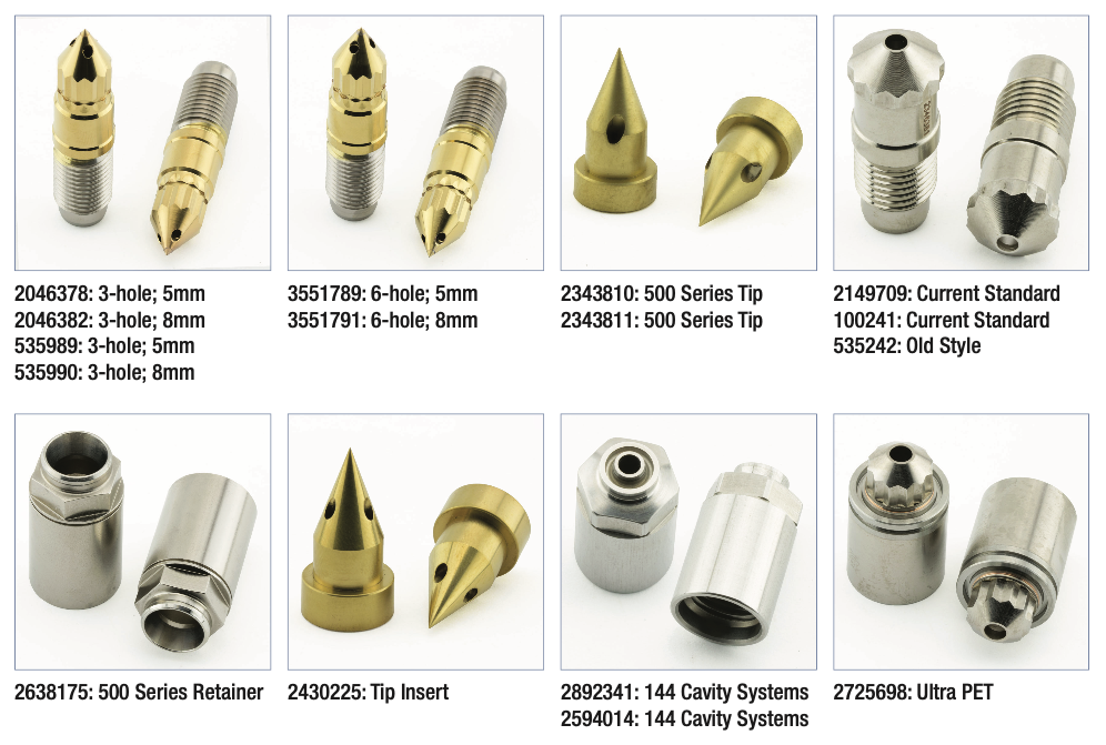
👉 View Nozzle Tips by Part Number: Standard, Non-Standard, & Custom Solutions
1. Single-Hole Nozzle Tips
Single-hole nozzle tips are among the most common configurations in hot runner systems. Melt exits through one central outlet, creating a straightforward and predictable path into the gate.
What they are used for
Single-hole designs are widely used in standard gating applications where one direct melt path is appropriate for the part and cavity design.
Why they remain common
They are simple, reliable, and easy to match when the original assembly is known. In many systems, they provide the most direct balance between flow control and replacement simplicity.
What matters most
The hole may be single, but the tip is not “generic.” Replacement still depends on matching:
- outlet diameter
- overall length
- body diameter
- sealing surfaces
- OEM/system-family geometry
Typical fitment context
Single-hole designs are common in replacement parts compatible with major OEM families such as Husky, Mold-Masters, MHT, Yudo, Milacron, and others, although the exact geometry varies by system.
2. Multi-Hole Nozzle Tips
Multi-hole nozzle tips use two or more melt outlets rather than one central opening.
What they are used for
These are typically used when the mold design or gate behavior benefits from distributing melt through multiple smaller outlets rather than one larger one.
Why they are selected
Multiple outlets can change how material enters the gate area and may help support particular filling patterns, gate shapes, or processing needs.
What matters most
With these designs, hole count is only part of the picture. Replacement also depends on:
- hole spacing
- outlet diameter
- outlet orientation
- total tip geometry
A multi-hole tip that looks similar may still behave differently if outlet placement changes.
3. Small-Orifice Nozzle Tips
Small-orifice nozzle tips are built with tighter outlet diameters for more controlled melt delivery.
What they are used for
They are commonly used when gate control, part appearance, or precise flow entry is important.
Why they are selected
A smaller orifice can help produce a more controlled gate area and may be helpful when minimizing excess material flow or managing vestige.
What matters most
Small outlets are less forgiving than larger ones. They can be more sensitive to:
- contamination
- degraded resin
- pressure rise
- shear sensitivity
- incorrect processing conditions
4. Large-Orifice Nozzle Tips
Large-orifice designs provide a less restrictive melt path through the tip.
What they are used for
These are commonly used where more flow volume is needed or where a less restrictive gate-entry condition is preferred.
Why they are selected
A larger outlet can help reduce restriction and pressure drop, depending on the application.
What matters most
Larger outlets are not automatically better. If oversized for the application, they can contribute to:
- poor gate control
- inconsistent vestige
- less stable shutoff behavior
- unnecessary process variation
The correct outlet size should always be treated as part of the original design intent.
5. Extended-Length Nozzle Tips
Extended-length nozzle tips are built with longer overall reach than standard alternatives.
What they are used for
They are used when the nozzle assembly and mold geometry require a longer projection into the gate area.
Why they are selected
In some systems, the distance between the nozzle body and the gate interface makes standard-length tips unusable.
What matters most
Length-specific tips are highly fitment-sensitive. Even small deviations can cause:
- poor seating
- improper thermal relationship at the gate
- leakage or interface problems
- assembly mismatch with surrounding components
This is one of the clearest examples of why exact dimensions matter as much as general style.
6. Large-Body or Heavy-Duty Nozzle Tips
Some nozzle tips are built around larger body dimensions or more robust section geometry.
What they are used for
These are often found in larger nozzle assemblies, more demanding production environments, or systems requiring a more substantial tip platform.
Why they are selected
A larger-body design can support certain thermal, structural, or fitment requirements that a smaller tip cannot.
What matters most
Even if the melt outlet appears similar to another tip, body size can prevent interchangeability. Buyers should verify:
- body diameter
- seating geometry
- mating features
- surrounding nozzle compatibility
7. Swaged Nozzle Tips
Swaged nozzle tips use a mechanically integrated construction method between the tip and its related body or assembly.
What they are used for
Why they are selected
These are commonly associated with specific OEM-defined or application-defined configurations where dimensional stability and assembly integrity are important.
What matters most
Swaged designs can provide a robust integrated configuration, particularly in high-output or geometry-specific systems.
This is not just a shape difference. Construction method matters too. A swaged design should be replaced with the correct corresponding construction style rather than a visually similar alternative.
8. Seal-Integrated Nozzle Tips
Some nozzle tips do more than deliver melt. Their geometry also contributes to sealing behavior in the assembly.
What they are used for
These are used where sealing integrity at or around the tip interface is a core part of system performance.
Why they are selected
When the tip plays a role in the sealing strategy, matching its exact geometry becomes especially important for leak prevention.
What matters most
These designs require close attention to:
- sealing faces
- contact surfaces
- material condition
- wear at the interface
- dimensional accuracy
9. Wear-Resistant Nozzle Tips
Wear-resistant nozzle tips are produced from materials, treatments, or surface strategies chosen to improve life in harsher molding environments.
What they are used for
They are often selected when processors run:
- abrasive materials
- filled materials
- long production campaigns
- applications with elevated wear stress near the gate
Why they are selected
The tip is exposed to repeated thermal cycling, pressure, and resin contact. In demanding environments, wear resistance becomes a major selection factor.
What matters most
Material choice should be evaluated alongside geometry. A wear-resistant tip still has to match:
- outlet pattern
- total length
- sealing surfaces
- thermal behavior
- OEM/system compatibility
10. OEM-Geometry-Specific Replacement Nozzle Tips
Many replacement nozzle tips are best understood not as generic style categories, but as exact geometry-specific parts designed around a particular OEM system family or original part reference.
What they are used for
These are used when the assembly requires a very specific combination of dimensions, outlet style, sealing features, and material properties.
Why they are selected
In practice, many nozzle-tip replacements succeed or fail based on exact geometry, not broad visual description. Two parts may look similar but perform differently because of subtle dimensional differences.
What matters most
This is where buyers should verify all of the following:
- OEM reference
- compatibility family
- total length
- body diameter
- outlet count
- outlet diameter
- sealing geometry
- material
- surrounding nozzle assembly details
As with the rest of our replacement hot runner parts, correct identification and compatibility matching matter more than broad visual similarity.
OEM Compatibility Contexts
When discussing hot runner nozzle tip configurations, it is often useful to frame them by the system families they are commonly associated with.
Depending on the exact design, nozzle tips may be sourced as replacement components compatible with systems associated with:
- Husky
- Mold-Masters
- MHT
- SIPA
- SACMI
- Yudo
- Milacron
- other major hot runner platforms
Fitment should always be confirmed by part reference, dimensions, gate style, and assembly design, not by OEM family name alone.
How to Match the Right Replacement Nozzle Tip
When sourcing a replacement nozzle tip, buyers should avoid reducing the decision to one variable such as part number family or outlet count.
A proper match usually requires checking:
- OEM reference or system family
- overall length
- body diameter
- outlet count
- outlet diameter
- sealing features
- material
- gate style
- surrounding nozzle compatibility
This is the same compatibility-first approach we apply across our aftermarket hot runner replacement parts.
Nozzle Tip Material
Geometry gets most of the attention, but material affects long-term performance too.
Depending on the application, nozzle tip material can influence:
- wear resistance
- resistance to deformation at operating temperature
- corrosion behavior
- service life in abrasive environments
- dimensional stability under repeated thermal cycling
Problems Caused by the Wrong Nozzle Tip Configuration
Using the wrong nozzle tip configuration can contribute to:
- inconsistent cavity filling
- drool
- stringing
- poor gate vestige
- leakage
- unstable thermal behavior
- faster wear
- more frequent maintenance
- recurring cosmetic variation
Nozzle tip condition and geometry affect real-world flow behavior and defect risk, not just fitment on paper.
Nozzle Tip Designs Vary Based on Intent
Hot runner nozzle tips are not one-size-fits-all components. From single-hole and multi-hole designs to differences in outlet size, body dimensions, sealing strategy, construction style, and wear material, each configuration is used for a reason.
For processors and maintenance teams, understanding these differences makes troubleshooting and replacement decisions more accurate. For buyers sourcing replacement components, it helps explain why correct nozzle-tip selection depends on more than a simple part reference or a visual match.
If you are evaluating replacement hot runner nozzle tips for systems compatible with major OEM hot runner platforms, the best approach is to confirm the original design intent, verify the critical dimensions, and match the exact configuration needed for reliable performance.
Polymer Cleaning Technology: Leading the Way in Hot Runner Services and Parts
With a reputation for precision and reliability, PCT helps manufacturers keep their hot runner systems operating at peak performance.
Services Offered
Hot Runner Cleaning
Specialized chemical-free cleaning systems remove polymer residue without damaging metal surfaces.
Hot Runner Maintenance
Thorough Inspection, Testing, Analysis, Assembly, and Comprehensive Reports.
Preventive Maintenance Programs
Tailored service schedules to suit production environments.
Component Repair & Refurbishment
Includes manifolds, heaters, nozzles, and temperature control systems.
Reverse Engineering & Custom Parts
Solutions for hard-to-find or discontinued OEM parts.
Parts Inventory
- Nozzle Tip Insulators
- Heaters (coils, bands, cartridges)
- Thermocouples
- Nozzle Tips
- Valve Pins
- Nozzle Housings
- Valve Bushings
- Pistons & Spacers
- Seal kits (O-Rings)
Related Reading
- Nozzle Tip Carbonization: How Micro Deposits Create Macro Defects
- Hot Runner Nozzle Maintenance & Troubleshooting Quick Guide
- Hot Runner Nozzles: Selection Guide & Common Problems
*This information is to be used as a general guideline only. Speak to your system manufacturer directly for verified information regarding your Hot Runner System.
*Note: All numerical data and performance examples in this article are drawn from a combination of published supplier datasheets, standard tool-steel references, and aggregated field experience. Where specific case studies are presented, they represent illustrative or typical outcomes, not a controlled laboratory test. Actual results may vary depending on resin chemistry, cycle conditions, and maintenance intervals.
References & Technical Sources
- RJG Inc. Material Degradation, Residence Time, and Gate Behavior
- Plastics Technology Magazine Hot Runner Maintenance & Gate Defect Diagnostics
- Mold-Masters Nozzle Tip Maintenance & Cleaning Guidelines
- Synventive Gate Contamination & Hot Runner Service Documentation
- SPE ANTEC Proceedings Carbon Formation and Polymer Degradation Studies
Find this information useful? Share with friends & colleagues:
Contact Information:
Polymer Cleaning Technology, Inc.
sales@polymercleaning.com
+1 (908) 281-0055