
Troubleshooting Nozzle Tip Insulation & Diagnosing Hot Runner Gate Defects
Updated August, 2026
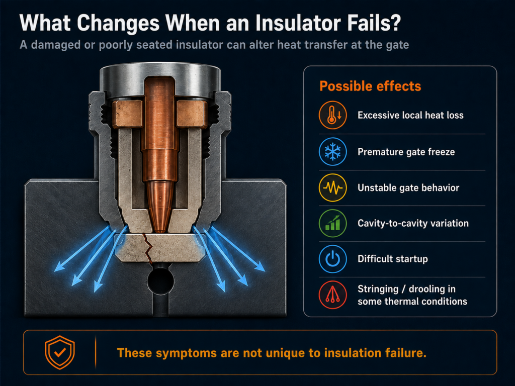
A damaged nozzle tip insulator can change the thermal relationship between the heated nozzle or tip and the surrounding mold/gate area. Depending on the hot runner design, that change may contribute to premature gate freeze, unstable gate behavior, cavity-to-cavity variation or other molding problems.
But a defect is evidence of a process condition, and not proof that one specific component caused it.
Stringing, drooling, short shots, black specks, burn marks, hesitation and temperature instability may also originate from the heater, thermocouple, controller, nozzle tip, gate, valve components, resin, process settings, contamination or another area of the hot runner system.
At Polymer Cleaning Technology (PCT), we specialize in diagnosing and resolving these exact issues. This brief guide provides information for manufacturers on hot runner troubleshooting, including identifying and correcting injection molding defects caused by faulty nozzle tip insulators, and how to keep your system running clean, consistent, and under control.

Contact +1 (908) 281-0055 or sales@polymercleaning.com to discuss your Hot Runner Systems today! Experts in Hot Runner System Repair and Maintenance for all OEM.
This guide focuses on one question:
Is the nozzle tip insulator actually contributing to the problem, or is something else creating the same symptom?
OEM designs differ substantially. Some systems use a physical nozzle tip insulator, while other designs can use an insulating resin region or another interface strategy. Husky, for example, documents systems where an insulating gate bubble performs thermal separation between the nozzle tip and colder cavity-plate steel instead of a conventional tip insulator.
Safety Note! Hot runner inspection and disassembly can expose personnel to high temperature, electrical energy, stored pressure, heavy mold components and residual molten polymer. Follow the system manufacturer’s procedures, plant lockout/tagout requirements and applicable safety practices. Inspection involving disassembly should be performed by trained personnel.
Quick Note: What Does a Nozzle Tip Insulator Do?
The exact function depends on the hot runner manufacturer and nozzle design, but nozzle tip insulation generally helps manage the thermal interface between heated nozzle components and cooler surrounding mold steel.
Good thermal separation is a fundamental requirement in hot runner design because the hot runner must maintain controlled melt conditions while operating inside a cooler injection mold. Resin-supplier technical guidance likewise identifies effective thermal separation between the hot runner and mold as an important hot-runner design consideration.
In some designs the insulator also has an important physical interface relationship with the nozzle tip and gate detail. Geometry, thickness, compression, orientation, cleanliness and seating may therefore matter in addition to the thermal conductivity of the material.
For example, Husky service documentation for specific hot runner families warns that additional resin beneath or on an insulator can alter the calculated preload during assembly, and that used insulators may carry geometry-specific witness marks from the tip and gate detail.
Quick Answer: What Happens When a Nozzle Tip Insulator Fails?
A nozzle tip insulator helps control heat transfer at the nozzle/gate interface in systems designed to use one. If the insulator is cracked, damaged, contaminated, incorrectly seated, dimensionally changed or otherwise unsuitable for the application, heat transfer and the physical relationship around the tip may change.
Depending on the design and failure mode, the result may contribute to:
- excessive heat loss,
- premature gate freeze,
- inconsistent gate behavior,
- startup difficulty,
- cavity-to-cavity variation,
- stringing or drooling under some thermal conditions,
- resin degradation or carbonization where abnormal heat history is also present.
None of those symptoms uniquely identifies the insulator.
The correct diagnosis requires comparing the suspected insulation problem against competing thermal, electrical, mechanical, material and processing causes.
What Does a Failed Nozzle Tip Insulator Look Like?
Physical evidence that deserves investigation may include:
- cracking,
- chipping,
- fractured or missing material,
- deformation,
- flattening or changed compression where applicable,
- damaged seating surfaces,
- resin contamination beneath or around the insulator,
- carbonized residue,
- uneven seating,
- visible misalignment,
- unusual witness/contact patterns,
- evidence of interference with the gate detail,
- a replacement component with different geometry or thickness,
- damage introduced during prior disassembly or cleaning.
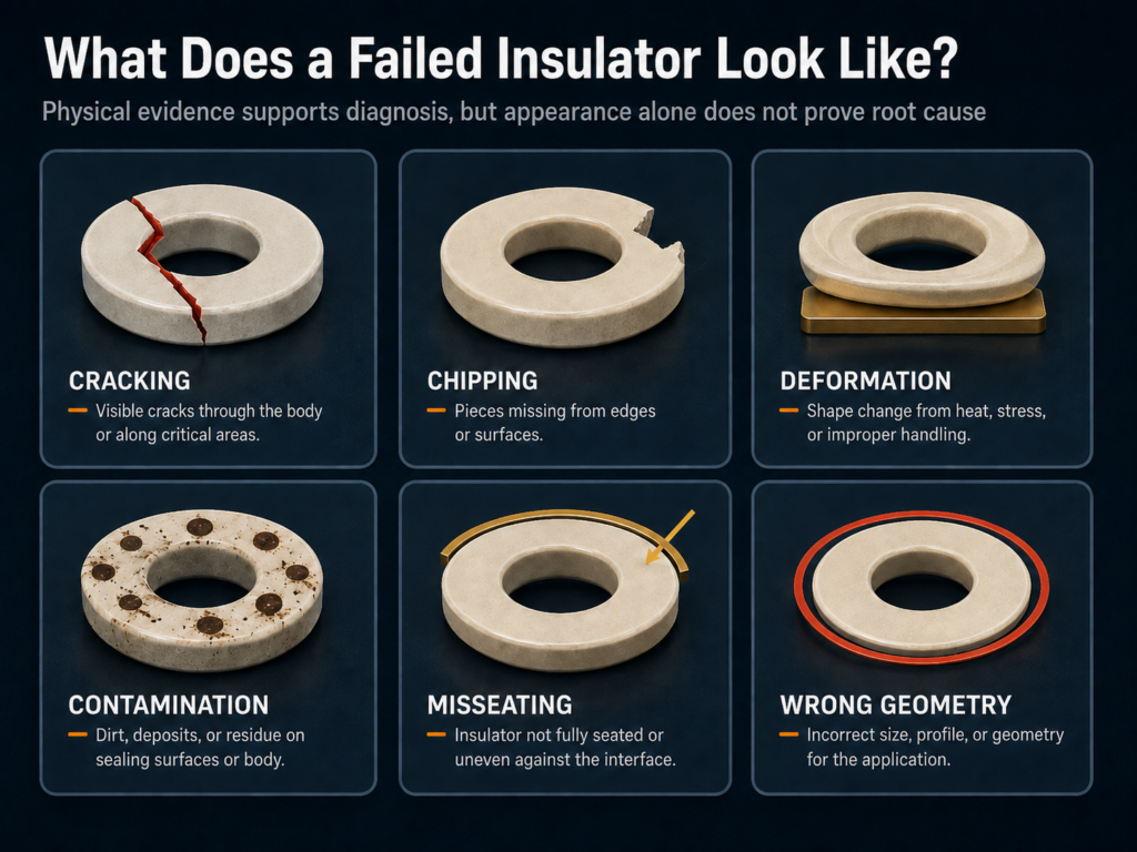
Physical damage is evidence, not the diagnosis.
A visibly damaged insulator may justify replacement, but it does not automatically prove that it caused the production symptom.
Likewise, an insulator that looks acceptable may still deserve investigation if:
- its dimensions are wrong,
- it is the wrong replacement part,
- its seating is incorrect,
- contamination is beneath the component,
- its relationship with the tip or gate has changed.
OEM documentation for specific Husky systems instructs technicians to investigate gate-insert dimensions and nozzle-tip position where resin is found around an insulator rather than simply replacing the component and assuming the problem is solved.
Common Defects Caused by Poor Nozzle Tip Insulation
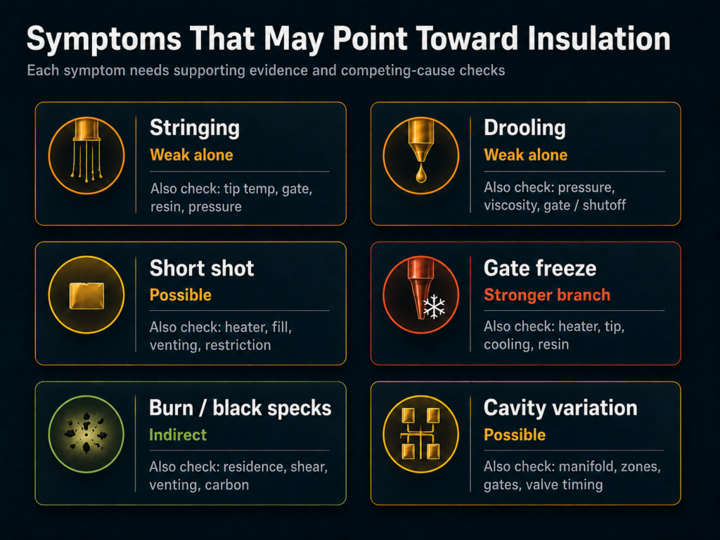
1. Stringing
Description: Thin strands of plastic trail from the nozzle tip between shots or hang from the part after ejection.
Cause: Excessive heat at the nozzle tip due to insulation failure allows plastic to drool out after injection, leading to string formation.
Troubleshooting:
- Check nozzle tip temperature against setpoint.
- Inspect insulation ring or tip seat for degradation.
- Replace cracked or worn tip insulators.
PCT Maintenance Tip: Polymer Cleaning Technology offers OEM-compatible replacement nozzle tip insulators that restore proper thermal isolation and eliminate heat creep.
2. Drooling
Description: Molten resin oozes from the nozzle tip during hold or idle phases, contaminating the mold or parting line.
Cause: A compromised insulator fails to maintain the thermal boundary, causing the nozzle tip to overheat and resin to leak.
Troubleshooting:
- Verify hold pressure and dwell time.
- Check for discoloration or burning at the nozzle tip.
- Install new insulators rated for your process temperature range.
PCT Maintenance Tip: Regular inspection of nozzle tip seats and replacement of insulators during scheduled outages prevents drooling and extends the life of surrounding components.
3. Short Shots
Description: The mold cavity does not fill completely, leaving incomplete or misshapen parts.
Cause: If insulation is damaged, the tip may lose heat too rapidly, causing resin to freeze prematurely at the gate.
Troubleshooting:
- Measure temperature delta from manifold to nozzle tip.
- Check for cold spots or heat sink effects at the mold interface.
- Replace any worn or missing insulation rings.
PCT Replacement Parts: PCT’s high-performance ceramic and mica-based tip insulators maintain stable tip temperatures even under high-cavity pressure environments.
4. Burn Marks or Splay
Description: Discolored streaks or cloudy defects appear on the molded part, often near the gate.
Cause: Intermittent overheating from poor insulation causes localized burning or excessive moisture vaporization.
Troubleshooting:
- Inspect nozzle tip for burn marks or carbonization.
- Use thermal imaging to detect hot spots.
- Replace insulation and recalibrate heater zones.
PCT Service Support: Our field technicians can perform on-site thermal diagnostics to pinpoint insulation failures and recommend corrective action.
5. Gate Freeze or Hesitation Marks
Description: Material freezes off prematurely or hesitates at the gate, causing surface defects or dimensional inconsistencies.
Cause: Inadequate insulation allows heat to dissipate too quickly into the cold mold steel.
Troubleshooting:
- Measure cycle time versus flow completion.
- Examine tip insulators for shrinkage, cracks, or loss of compression.
- Install new OEM-spec insulators.
PCT Advantage: Our nozzle tip insulators are designed for easy integration with most major hot runner brands including Mold-Masters, Husky, Synventive, and Incoe.
Diagnosing Defects: Nozzle Tip Insulator or a Larger Problem?
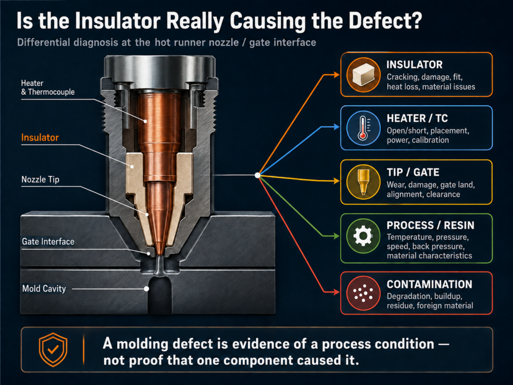
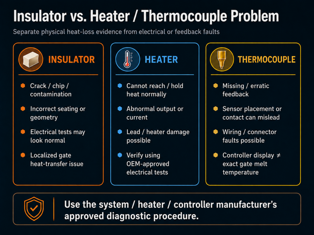
Insulator Failure vs. Heater, Thermocouple or Control Problem
| Potential Problem | Typical Evidence | Controller Behavior | Physical Evidence | Inspect Next |
|---|---|---|---|---|
| Damaged insulator | Local gate behavior changes; problem may follow service or physical damage | May appear normal | Crack, chip, deformation, contamination, incorrect seating | Tip/insulator/gate interface |
| Failed heater | Zone cannot produce required heat normally | Alarm, abnormal output or inability to reach/hold target may occur | Lead or heater damage may be visible | OEM-approved electrical testing |
| Degraded heater / poor thermal contact | Slow or abnormal thermal response | Higher or unusual heater demand may occur | Not always visible | Heater fit, electrical condition and trend |
| Open thermocouple | Loss of usable feedback | Fault/alarm depending on controller | Damaged leads/connection possible | TC circuit and connection |
| Poorly contacting/mislocated TC | Displayed temperature may not represent the critical location well | Zone may appear stable despite an actual thermal problem | Installation issue may be visible after access | Sensor position/contact |
| Wiring/connector fault | Intermittent or incorrect electrical behavior | Erratic reading/output possible | Connector, lead or pin damage | Wiring and termination |
| Controller-zone issue | Symptom follows control channel rather than physical drop | Abnormal control behavior | Usually no gate-interface damage | Controller/wiring diagnosis |
| Physical heat loss with normal electrical system | Electrical checks may appear acceptable but gate behavior remains abnormal | Controller may compensate with increased output | Insulator, contact, seating or mold-interface issue possible | Mechanical/thermal interface |
Watlow recommends inspecting and electrically testing compromised temperature sensors rather than diagnosing them from a process defect alone, while PCT maintains a separate Heater and Thermocouple Health resource for deeper electrical troubleshooting.
Important principle
Note: The controller displays the temperature measured at the sensor location. It does not directly prove the exact melt temperature at every point near the gate. That distinction is one reason physical heat-transfer problems can sometimes coexist with apparently stable controller readings.
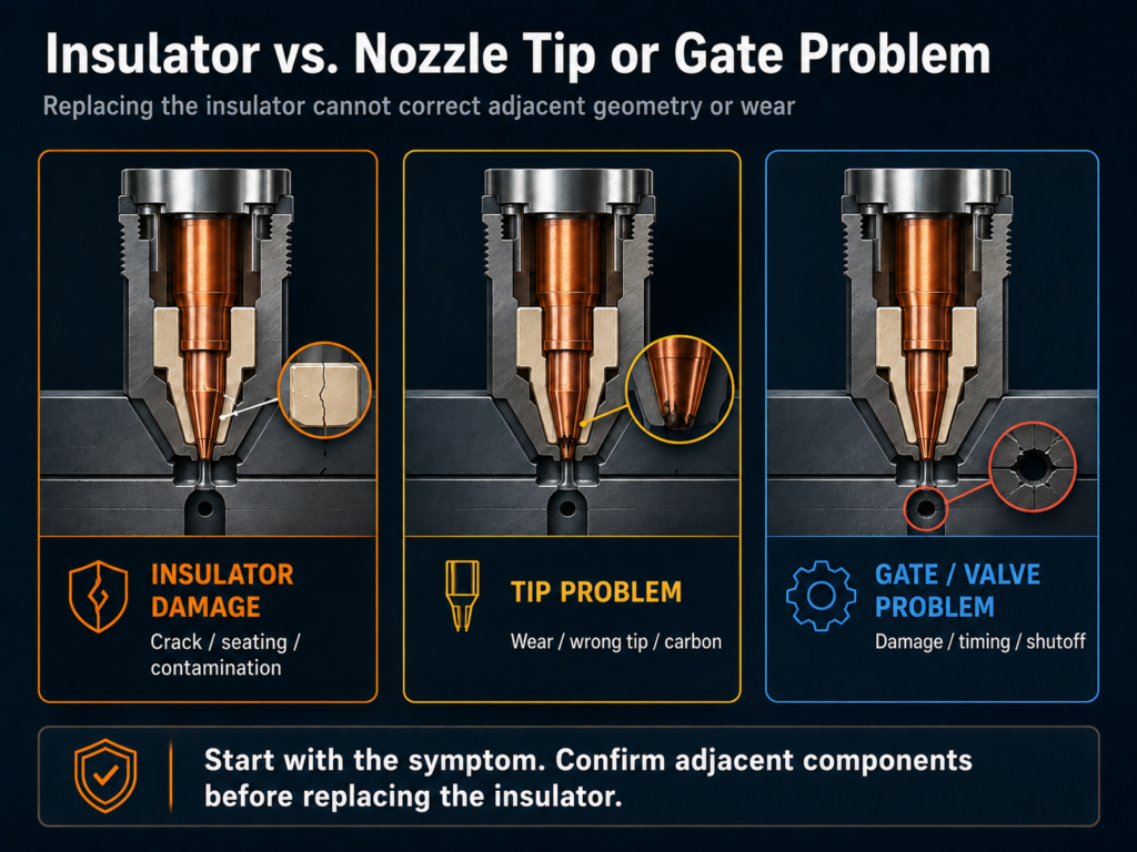
Insulator Failure vs. Nozzle Tip or Gate Problem
Before replacing an insulator, determine whether the problem actually belongs to the neighboring precision components.
A worn or damaged nozzle tip can produce
- changed gate behavior,
- leakage,
- inconsistent shutoff,
- changed flow characteristics,
- carbon accumulation,
- altered gate vestige.
An incorrect nozzle tip can produce
- an unsuitable tip-to-gate relationship,
- incorrect flow area,
- altered thermal behavior,
- mechanical interference,
- sealing problems.
A damaged gate can produce
- premature restriction,
- leakage,
- vestige problems,
- imbalance,
- poor pin shutoff,
- inconsistent freeze-off.
A valve-pin or bushing problem can produce
- incomplete shutoff,
- stringing,
- drooling,
- gate damage,
- timing inconsistency,
- leakage.
Replacing the insulator cannot correct incorrect tip geometry, a damaged gate or a valve component that no longer operates as designed.
Root Cause Analysis: How Nozzle Tip Insulators Fail
Mechanical Damage
Potential mechanisms include:
- impact during handling,
- chipping during removal,
- damage from unsuitable tools,
- incorrect assembly,
- misalignment,
- uneven loading,
- damaged mating surfaces.
OEM documentation emphasizes careful removal and protection of nozzle-tip and sealing surfaces during insulator service.
Seating and Interface Problems
A serviceable component can still perform poorly if it is installed incorrectly.
Possible issues include:
- contamination beneath the insulator,
- incorrect orientation,
- uneven seating,
- incorrect compression or preload,
- mismatched geometry,
- damage to the gate-side interface.
For certain Husky designs, resin contamination around the insulator can change assembly preload, and previously compressed insulators can be specific to their prior tip and orientation.
The exact requirement is system-specific.
Contamination and Carbonization
Residue may interfere with:
- seating,
- dimensional relationship,
- thermal transfer,
- gate geometry,
- sealing.
Do not assume the residue originated at the insulator.
It may have come from upstream degradation, leakage, an improperly cleaned tip, previous maintenance or another melt-flow region.
Incorrect Replacement Component
A visually similar insulator is not proof of interchangeability.
Depending on the design, compatibility can require the correct:
- dimensions,
- geometry,
- thickness,
- material,
- fit,
- thermal properties,
- system family,
- tip relationship,
- gate relationship.
Thermal and Service Exposure
Repeated operating cycles, abnormal temperature exposure and the material’s own limits can eventually affect some insulation components, but the applicable failure behavior varies by material and design.
Symptom → Root‑Cause (Quick Reference Table)
Use this table on the shop floor for rapid diagnosis.
| Symptom | Most Likely Insulator-Related Root Cause | First Diagnostic Check | Immediate Corrective Action |
|---|---|---|---|
| Stringing / Threads | Heat creep from poor insulation, seated gap | Measure nozzle-tip temp vs setpoint; visual inspect insulator | Replace insulator; reduce idle temp; purge if resin degraded |
| Drooling / Oozing | Overheated tip; insulation failure | Check hold pressure/dwell; inspect for burned insulator | Replace insulator; lower tip temp; adjust hold profile |
| Short shots | Tip heat loss (cold spot), gap or missing insulator | Measure ΔT manifold → tip; check seating | Re-seat/replace insulator; increase tip heat or shorten flow path |
| Burn marks / Splay | Localized overheating / stagnant melt | IR scan for hotspots; inspect tip for carbonization | Replace tip/insulator; purge and reduce dwell temp |
| Gate freeze / Hesitation | Excessive heat dissipation into mold | Check tip fit and compression; inspect for cracks | Replace insulator; retorque to spec; verify gate temp profile |
Diagnostic Methods & Instrumentation (How to Measure & Interpret)

Instruments & Use
- Thermocouples: Best for continuous monitoring. Place as close to the nozzle tip as OEM allows (within 1–3 mm for tip probes). Use properly rated (K-type or as specified) thermocouples and log data for at least 50 cycles to spot drift.
- Infrared (IR) Camera: Use to image multiple nozzles at once to find hot/cold anomalies. Set emissivity for steel/ceramic surfaces (typical 0.6–0.9 depending on finish). Take comparative images during steady-state.
- Borescope: Use 3–6 mm diameter borescope with LED illumination to inspect tip‑to‑seat interfaces and reveal cracks or carbonization inside tight areas.
- Multimeter / Resistance Meter: Test heater continuity and resistance; compare recorded values to OEM nominal. A sudden open circuit or resistance outside ±15% of nominal indicates failure or abnormal heat path.
- Data Loggers / SCADA: Trend gate tip temperature, shot weight, pressure, and cycle time for early‑warning detection.
Interpretation Thresholds (Guideline — confirm with OEM)
- Tip‑to‑Manifold ΔT: A drop greater than 8–12 °C between manifold and tip typically warrants an insulator inspection. (Thresholds depend on system/design; use OEM values when available.)
- Between‑cavity Variation: Tip temp variation >±3 °C across cavities indicates uneven insulation or seating problems.
- Heater Resistance Deviation: Resistance deviation >±15% from nominal suggests heater degradation or abnormal heat flow.
- Thermocouple Drift: Replace thermocouples if repeated calibrations show drift >±2 °C.
Practical Tips
- Record baseline images and measurements on commissioning — compare new data against baseline to detect slow failures.
- Always perform thermal scans under steady‑state conditions (after several production cycles) to avoid false positives during ramp‑up.
Material & Design Considerations for Tip Insulators
Alumina Ceramic (Al₂O₃)
- Pros: Excellent thermal barrier, high temperature stability, excellent chemical resistance.
- Cons: Very brittle (can crack if mishandled), requires careful seating and torque control.
- Best for: High‑temperature resins, long continuous runs where thermal isolation is critical.
Mica Composites
- Pros: Good thermal stability, less brittle than ceramic, decent mechanical compliance for variable seating.
- Cons: Slightly higher thermal conductivity than alumina; may char if overloaded.
- Best for: Applications requiring moderate temperature isolation with improved impact tolerance.
High‑Temp Polymer / Composite Insulators
- Pros: Better mechanical resilience, less brittle, easier to machine and seat.
- Cons: Lower maximum temperature capability compared to ceramics; may be more susceptible to resin attack at extreme temps.
- Best for: Lower to mid-temp resins or where frequent handling and replacement is expected.
Design Notes
- Choose insulators rated for continuous exposure at your operating temperature; margin of 20–50°C above process temp reduces risk of early failure.
- Consider insulator geometry that supports even compression and avoids point loads that may crack ceramic rings.
Preventive Maintenance & Lifecycle Guidelines
Inspection & Replacement Matrix
| Condition / Resin Type | Visual Inspect | Temp Check | Disassembly & Clean | Replace Insulator |
| Standard resins (PE/PP/ABS) | Daily | Weekly | Quarterly | 12–24 months or 5k–10k cycles |
| High‑temp/engineering resins (PC/PEI/PPS) | Daily | Bi‑weekly | Monthly | 6–12 months or 2k–5k cycles |
| Filled / abrasive (glass/mineral filled) | Per shift | Weekly | Monthly or per run | 3–12 months depending on abrasion |
Additional Guideline Suggestions
- Condition‑based replacement: Replace immediately when cracks, chipping, or ΔT thresholds are exceeded.
- Spare inventory: Keep at least 1–2 complete sets of insulators for each mold/Nozzle type on‑site.
- Lifecycle logging: Track installation date, cycles, resin types, and failure mode to build a predictive replacement model.
Integration with Hot Runner Controls & Adaptive Algorithms
Modern hot runner controllers can assist in diagnosis and compensation for insulation issues.
What Controllers Can Do
- Zone balancing: Keep manifold and tip zones coordinated to reduce thermal gradients.
- PID autotune: Controllers with autotune can respond faster to disturbances; however, persistent offset after PID tuning points to mechanical/insulation issues rather than control problems.
- Alarm limits: Set tiered alarms (e.g., warning at ±3 °C, critical at ±8–12 °C) for tip temp deviation to trigger inspection workflows.
- Trend logging & analytics: Use embedded analytics or SCADA to detect slow drift in tip temperatures or heater current that may indicate insulation degradation.
How to Use Controls in Troubleshooting
- When a tip shows drift, temporarily swap controller zones (if safe and possible) to isolate whether the fault is in the controller wiring/heater or the physical insulator.
- Use controller‑logged heater current and resistance readings as part of the root cause analysis.
Troubleshooting Steps for Manufacturers
Step 1: Visual Inspection
Begin with a shutdown inspection of nozzle tips. Look for signs of:
- Carbon build-up
- Discoloration or charring
- Broken ceramic or mica components
- Gaps between tip and seat
Use a borescope if necessary for hard-to-reach cavities.
Step 2: Temperature Profiling
Use thermocouples or infrared imaging to chart heat consistency from the manifold through to the nozzle tip.
- A drop of more than 10°C may indicate insulation failure.
- Uneven tip heating across cavities suggests uneven wear or poor fit.
Step 3: Replace and Reset
If issues are detected:
- Replace damaged or aged nozzle tip insulators with PCT-approved replacements.
- Ensure proper seating and torque according to OEM specs.
- Recalibrate tip and gate temperatures.
Step 4: Monitor and Document
Post-maintenance, continue to log performance metrics:
- Scrap rate
- Cycle time
- Gate temperature stability
Use this data to adjust your maintenance frequency and replacement cycle.
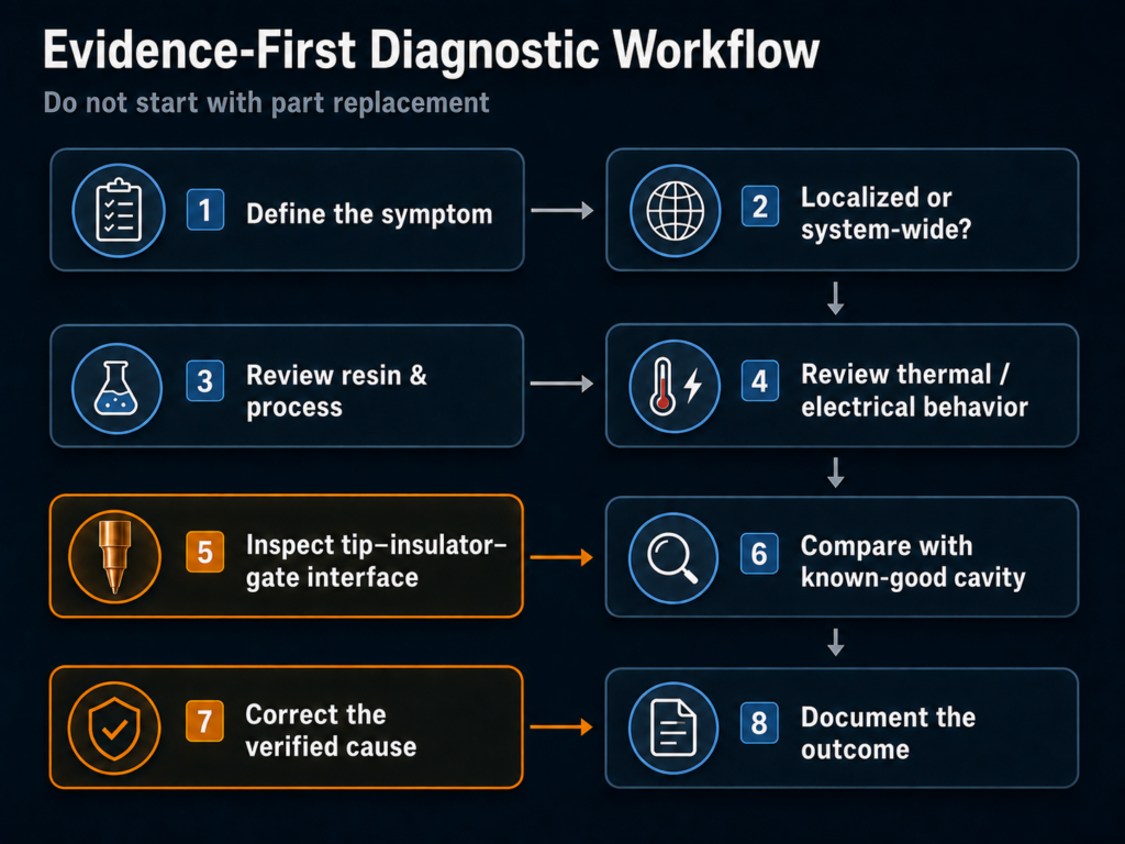
Advanced Troubleshooting Flowchart (Example)
Quick decision path for technicians – use this during the shift!
- Observe symptom on machine (stringing, drooling, short shot, splay).
- Perform visual check of nozzle tip (LOTO first).
- If cracked/chipped/burned → Replace insulator → re‑test.
- If visually clean → go to step 3.
- Check tip temperature vs manifold (stabilized run):
- ΔT > 8–12 °C or tip variance >±3 °C → suspect insulation or seating → remove and inspect.
- ΔT normal → test heater resistance and thermocouple continuity.
- Heater or thermocouple out of spec?
- Yes → Repair/replace electrical component, re‑test.
- No → Review mechanical seating, contamination, or resin degradation.
- If persistent after insulator replacement and heater test → escalate to thermal audit or send part for professional thermal cleaning/resurfacing
Suggested Maintenance Services from Polymer Cleaning Technology
PCT offers a full suite of services to help prevent and correct insulation-related molding issues:
1. OEM-Compatible Tip Insulators
We manufacture and stock high-performance nozzle tip insulators that match or exceed OEM specifications for most major hot runner systems. Materials include:
- Alumina ceramic
- Mica composites
- Advanced high-temp polymers
2. Thermal Audits
Our service techs are able to perform thermal diagnostics using infrared cameras and embedded sensors to detect insulation failures before they become major defects.
3. Scheduled Maintenance Programs
PCT’s preventive maintenance packages include inspection, cleaning, and replacement of critical hot runner components on a recurring basis tailored to your molding schedule.
Polymer Cleaning Technology: Leading the Way in Hot Runner Services and Parts
With a reputation for precision and reliability, PCT helps manufacturers keep their hot runner systems operating at peak performance.
Services Offered
Hot Runner Cleaning
Specialized chemical-free cleaning systems remove polymer residue without damaging metal surfaces.
Preventive Maintenance Programs
Tailored service schedules to suit production environments.
Component Repair & Refurbishment
Includes manifolds, heaters, nozzles, and temperature control systems.
Reverse Engineering & Custom Parts
Solutions for hard-to-find or discontinued OEM parts.
Parts Inventory
- Nozzle Tip Insulators
- Heaters (coils, bands, cartridges)
- Thermocouples
- Nozzle Tips
- Valve Pins
- Nozzle Housings
- Valve Bushings
- Pistons & Spacers
- Seal kits (O-Rings)
If your hot runner system is showing signs of erratic flow, cosmetic defects, or unpredictable cycles, poor nozzle tip insulation might be to blame. These small components play a big role in the thermal performance of your system. With the right diagnostics, quality replacement parts, and ongoing maintenance, you can bring consistency back to your injection molding process.
Polymer Cleaning Technology is here to help you every step of the way – with high-performance insulators, expert service, and preventive strategies to keep your line running clean and trouble-free.
Additional Resources
Plastics Technology Magazine – Troubleshooting Short Shots (https://www.ptonline.com)
Husky Injection Molding Systems – Nozzle Maintenance Recommendations (https://www.husky.co)
Mold-Masters Technical Library (https://www.moldmasters.com)
“Injection Molding Defects: Troubleshooting Guide” (A. Ibeh, Elsevier, 2021)
*This information is to be used as a general guideline only. Speak to your system manufacturer directly for verified information regarding your Hot Runner System.

Find this information useful? Share with friends & colleagues:
Contact Information:
Polymer Cleaning Technology, Inc.
sales@polymercleaning.com
+1 (908) 281-0055
